I've started assembling the first part of my clock circuit. I decided to partly follow the steps of Ben Eater.
I'll have a variable clock using a LM555, then a push button to step one instruction debounced with an LM555, and then a push button to select between the two debounced with an LM555.
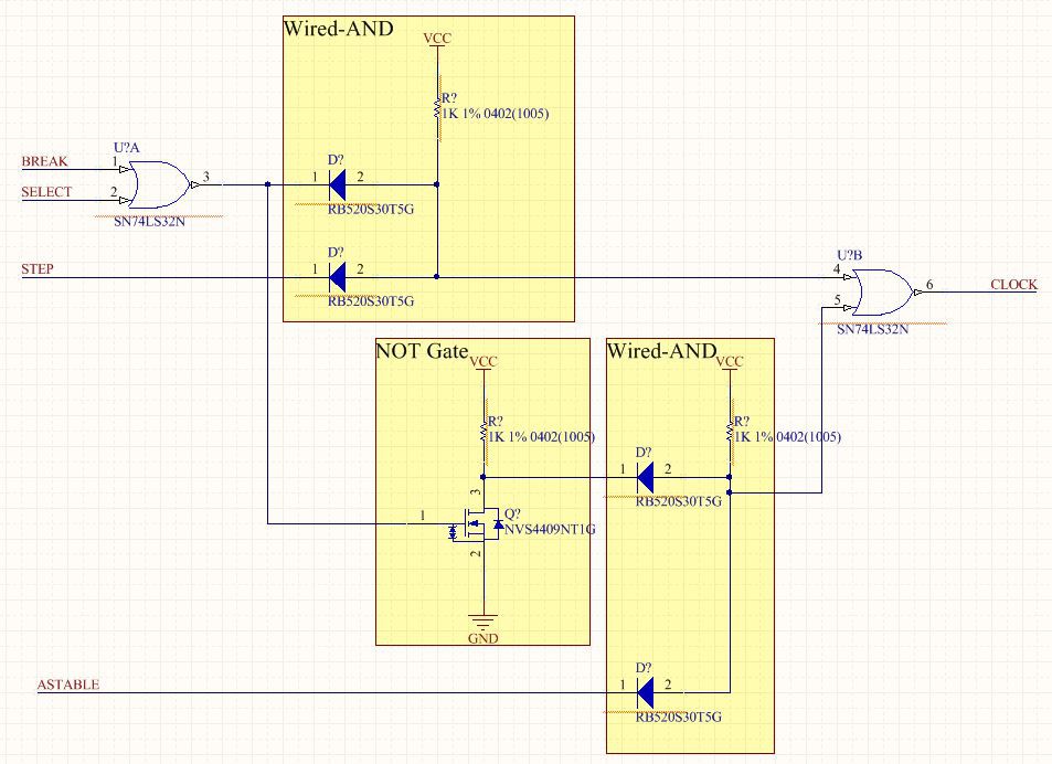
However, I'm departing a bit after that. He has a HALT command to stop the clock until a reset is performed. I think it's more useful to have a BREAK command to stop the clock. The clock can still be manually stepped if the BREAK line is high. This allows you to step past the BREAK command and continue operation. So this can be used as a debug function instead of just stopping the processor until reset. I worked out the digital logic and it looks something like this:
I wanted to add one more thing: this is a bad way to design a clock circuit. There can still be glitches when switching between clock domains. If the clock pulses high, then the select line immediately switches to the step mode, there can be a timing violation in the flip-flops (clock too-short). So some flip-flops will switch state and some will not. I haven't fixed it, but I may later.
Discussions
Become a Hackaday.io Member
Create an account to leave a comment. Already have an account? Log In.