 c.Invent
Before starting, you can find all the Solidworks source files from the project files or directly here.
This log is not about 3D printing Keymu's body (there will be dedicated build instructions) but about presenting the mechanical design and discussing the different main parts. The design is fully functional but there is a lot of room for improvement, as you'll see. In fact we are currenty working on improving this design thoroughly for the next iteration.
Solidworks
Why Solidworks? I know Fusion360 is the big thing right now but I simply already had a bit of experience with Solidworks so I simply went with what I already knew. So without further ado, lets jump into the design.
PCB
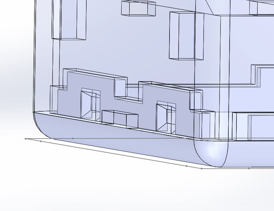
First things first: before starting dressing it up, the PCB needs to be 3D modeled in the most accurate way possible. It is quite easy with Eagle to output an pretty decent 3D model of the board and components. Simply hit the "IDF to 3D" button in the board view and follow the instructions.
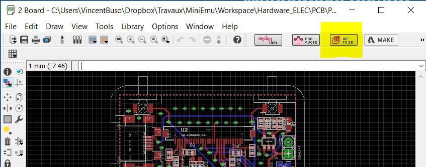
Even better is to set and fill an attribute "HEIGTH" to your components in Eagle before exporting to 3D, that way even if the components are modeled by bouding boxes, they'll automatically have the right height.
The IDF file can be directly imported into CircuitWorks, and the bounding boxes simulating the components should be sufficient to develop the 3D case. However if you would like to makes things more real, most of the components 3D source files can be downloaded right from Digikey or from the constructors websites. Simply replace the bounding boxes by these models, this is what I did with the most important components:
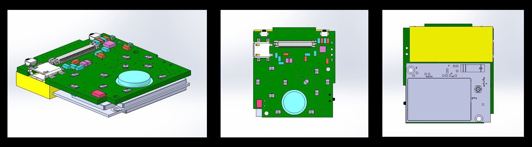
As you can see I left the bounding boxes for the battery, the speaker and all the passive components (making sure they were the right height though).
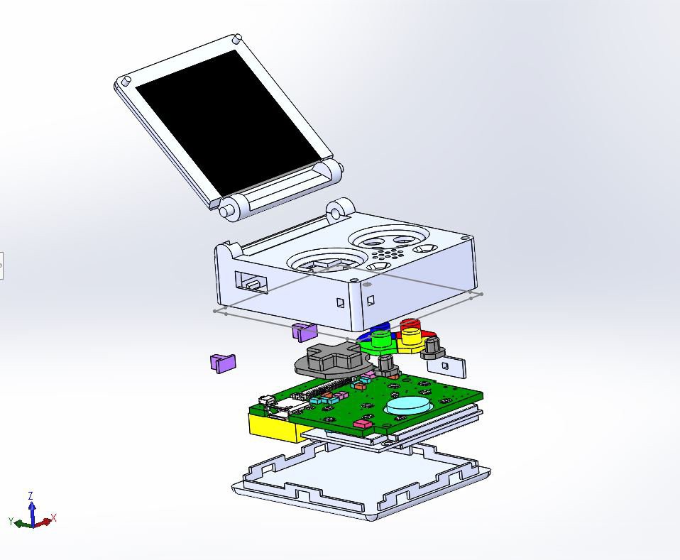
Snap/fit
Keymu is designed to be put together without screws, it's all snap/fit parts:
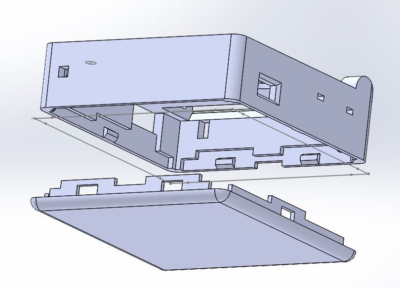
I was a bit sceptic at first, thinking that there would be some wiggling or even fearing that the parts would break but with tolerances around 0.020mm I was very happy with the results. The bottom and middle part fit together really well, in fact they do not wiggle at all and I have tried throwing them against walls a couple of times, they do not break nor disassemble.
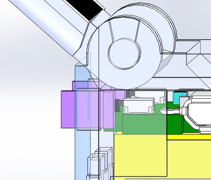
Hinge
The hinge was also designed so that its two parts - the screen casing and the main middle part - would slide in its socket on one side and snap fit together on the other:
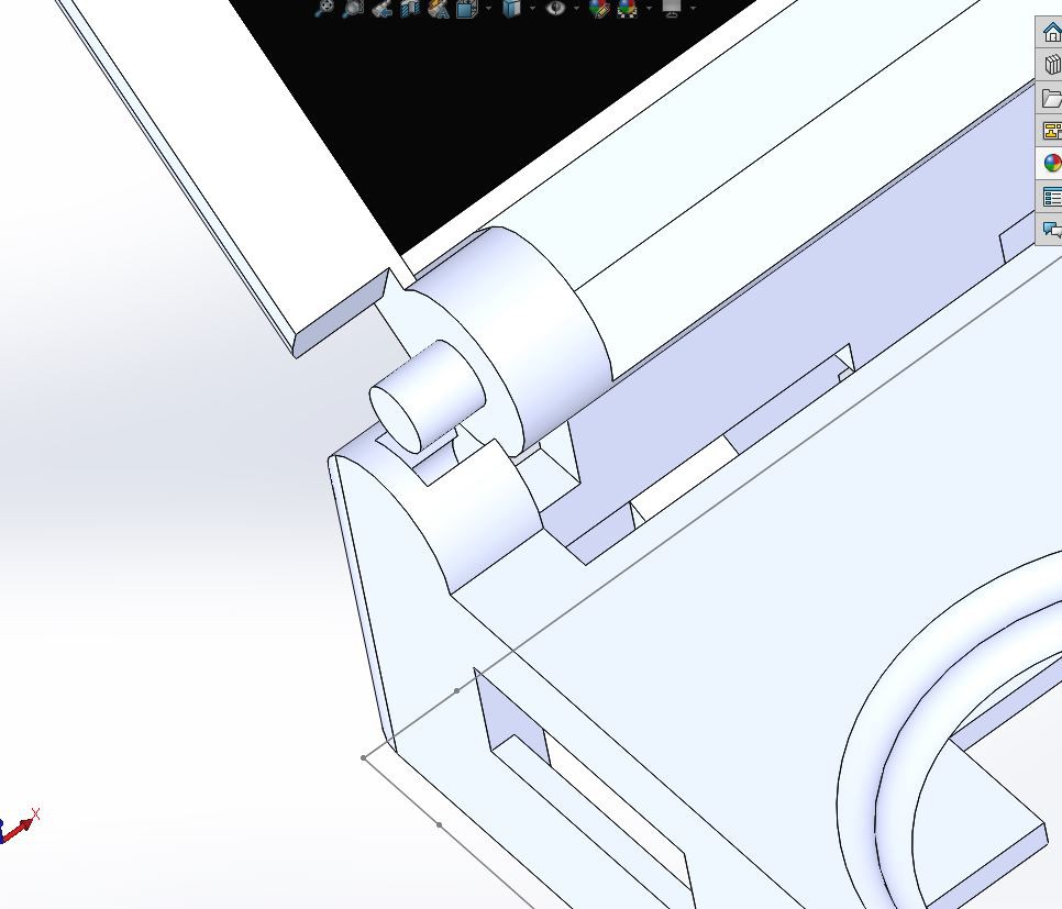
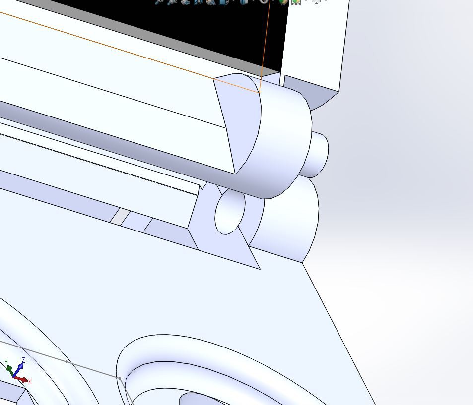
This is NOT optimal for many reasons: for starters it is obviously fragile, it is also not very easy to 3D print, there is no controlling the force of the rotation, and most importantly, the OLED flex cable is folded in two everytime the screen opens or closes.
So why what it designed that way? Well, if you look at how our old clamshell phones work or even if you open up a good old GBA SP, you'll see that most of the "active hinges", that is to say hinges designed for passing electrical wires through them, are designed pretty much always the same way. The flex PCB of the screen enters inside the hinge part from one of the 3D case travels through this hinge part inside the hinge part from the other 3D case, and enters the other 3D case from there. Most of the time the flex cable inside the hinge parts is already rotated, so basically when you open or close the screen, nothing bends or folds, it just follows the already designed rotation.
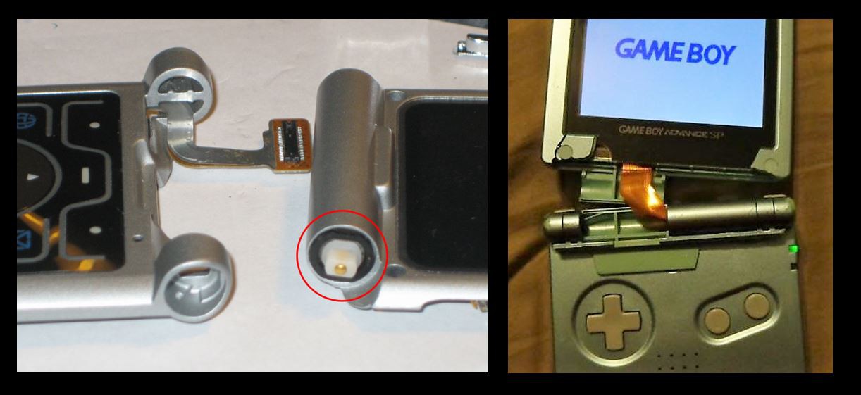
This is all good and well but this means flex cables are designed especially for our needs and most importantly with a width of around 4-5 mm max proportionnal to Keymu. The 1.5" OLED screen in Keymu is sadly not designed for active hinges and it is 28mm wide...while Keymu's width is 42 mm. This leaves around 7 mm around each side of the flex cable, hence the choice of this simple but effective design instead.
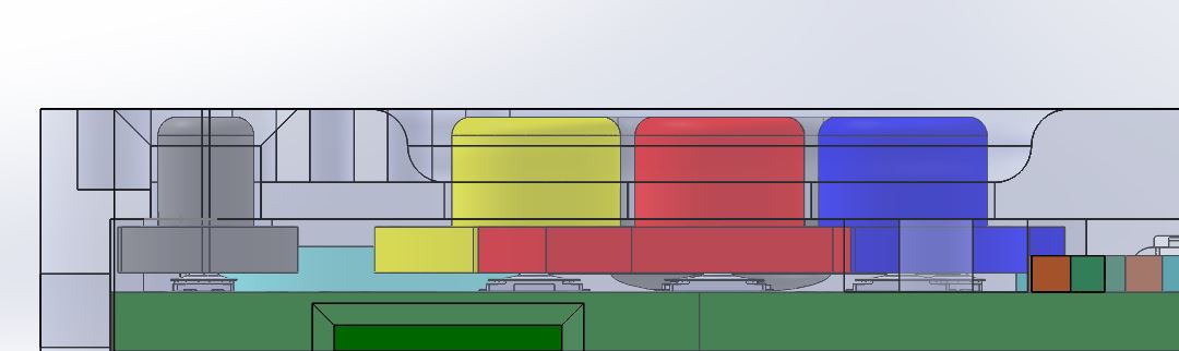
Main Buttons
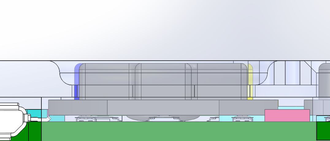
The main buttons are independant and rest directly above the panasonic tactile switches. Same thing with the arrows, appart this time this is a whole block supported not by the tactile switches but by its central spherical part.
When I started building Keymu people told me that it would be too small to play, and the buttons impossible to click without getting finger cramps. In fact I thought so too, but I figured it wouldn't matter if I couldn't play, Keymu would be cute as hell anyway.
This is wrong.
After I built Keymu, I realised two things: that it was actually not that hard to play with and that the current design could actually be optimized tenfold, for an even better playing experience. Now that we are working on the improved version, I have to say that is totally possible to play on this thing, and - in a lazy way - quite enjoyable actually since the thumbs just push and practically do not have to move... it's not easy to explain so I guess when you'll finish building your own Keymu you won't have to just take my word for it.
But let's talk about everything that can be improved in the current version:
- The visible part of the buttons is too high (2mm), this should be reduced to at least half of that for two reasons: it would reduce the whole height of Keymu of 1mm, and having buttons too high leaves too much space for the thumb to "fall under", height that need to be "climbed" again when hitting another button. It's not practical.
- The total course of these microscopic tactile switches is close to nothing. When clicking on the buttons, one feels a little "click" and that's it, no real "buttony" feeling! It's just frustrating for two reasons: a console button shouldn't click, it should be soft, and the course should be felt.
- The tactile switches under the arrow should be closer from the center of each branch (not at the end like now)
- The arrow could be completely replaced by four independant arrow shaped buttons for a better feeling.
As you can see, there's a lot of room for improvements here and, in my opinion, it is Kevin Bates from Arduboy who found the best possible configuration with the snap domes instead of the tactiles switches or silicone keys.
LR Buttons
Finally let's talk about these LR buttons:
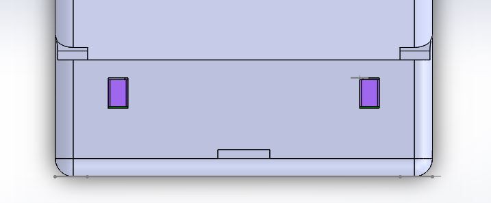
I am not very proud of them, I have to admit it. They are plain ugly but they do the job and for a first prototype that's what counts.
Now the room for improvement here is... let's say that it's not a room but a big ass mall. It's basically inviting you to propose a better solution (quick suggestion: full bottom corners buttons would be amazing).
Discussions
Become a Hackaday.io Member
Create an account to leave a comment. Already have an account? Log In.