 willbaden
The boards are finally finished. This was a long time coming, but I could machine the pcb's (which I have been wanting to do pcb milling for quite some time, but things did not fall into place until now) the mill have to become operational. The mill is a Chiron FZ08W that needed to have 3 phase hookup. The shop that I use has the 3 phase by the shop but not fed to it. Hopefully this will happen in the future, but for now, my former employer allowed me to borrow his 3 phase motor and some phase converter capacitors. Here is a picture of the box that I roughed in and placed on an old copy machine frame.
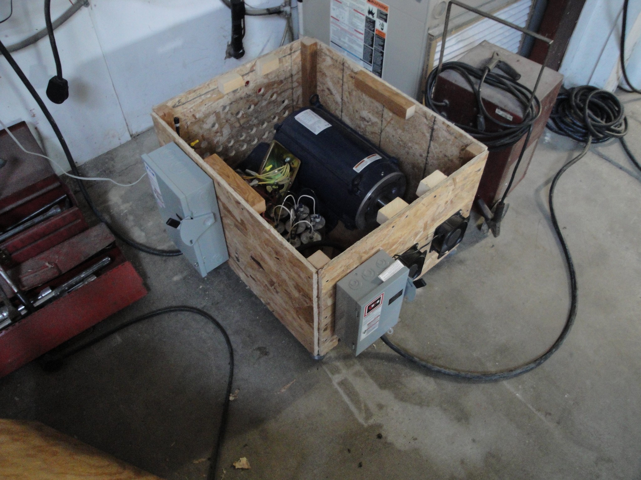
It has a single phase fused 60 Amp disconnect for the main feed in. This goes to the phase starter, capacitor bank and 3 phase 20 HP motor. From there it goes out to a 3 phase 30 amp disconnect that feeds the machine. There are two 120V fans to help with the cooling of the motor. I have plans to move them to be near the side of the motor casing since the cooling is not adequate in the position they are currently.
Once that was up and running, the boards had to be designed. I used the free version of Eagle as that is what I was taught way back when. From there I used the pcb to gcode converter. This is quite handy, but when the CNC has a limited amount of memory storage (not desktop computer, but instead a 21M FANUC controller) then the size becomes an issue. I had not setup the DNC drip feed yet which would allow for line by line feeding, so I ended up breaking up the programs into separate smaller programs.
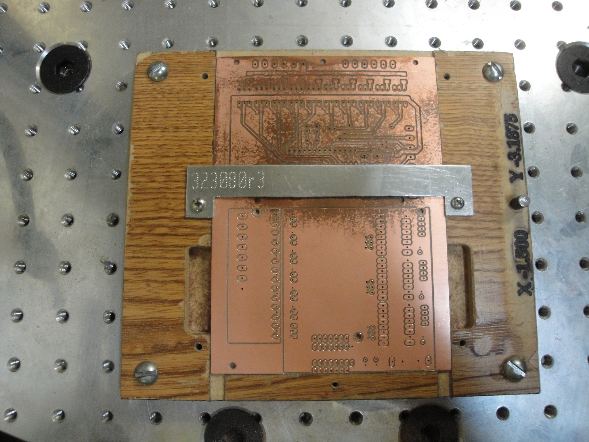
For the fixture, I used just a piece of cheap shelving board. It is quick and easy to machine and it machines without coolant. Here is a picture of a pcb after machining still sitting in the fixture.
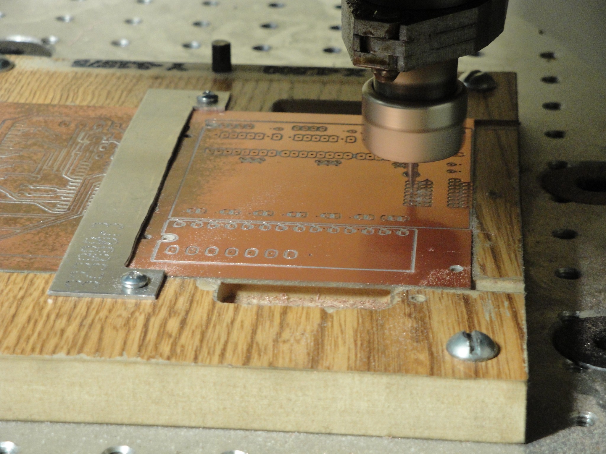
And here is a picture of it being machined:
Now my machining skills required some dusting off along with learning a new material. The problems I ran into:
1. PCB board not flat within .002". With the pcb mounted to the fixture, it would deflect up to .010". This is not good when trying to make a nice finish. The first cut of the controller board came out poorly. The copper was pushing a pretty heavy burr. This required using a honing stone to get rid of them. To prevent pushing a burr on the next cut, I raised the z offset until it would just cut the copper and not the fiberglass? beneath. Once I finished that program I looked to see if it had cut all the way through across the board. If not, I would lower the z offset by .0015" and rerun the same program. Repeat until the traces were cut out. I found this to work and keep from pushing a burr on warped/deflected boards. Very long and tedious process. If I do this again, I will plan on using a vacuum table or double sided tape.
2. Played with speeds/feeds. I ended up with 9500 RPM and 9-10 ipm. The max spindle speed I have is 10000 but wanted to keep from using the limits. 9-10 ipm was leaving a good finish.
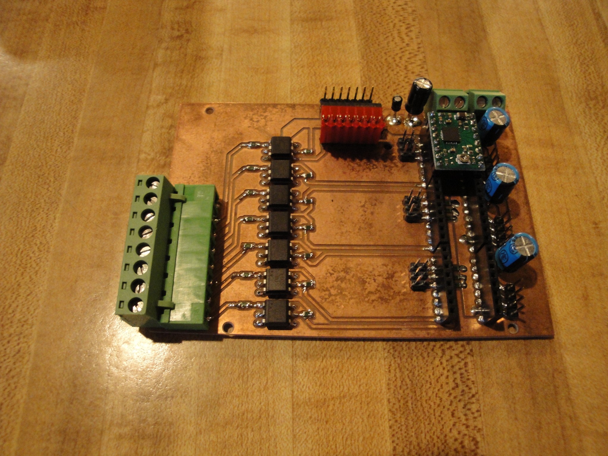
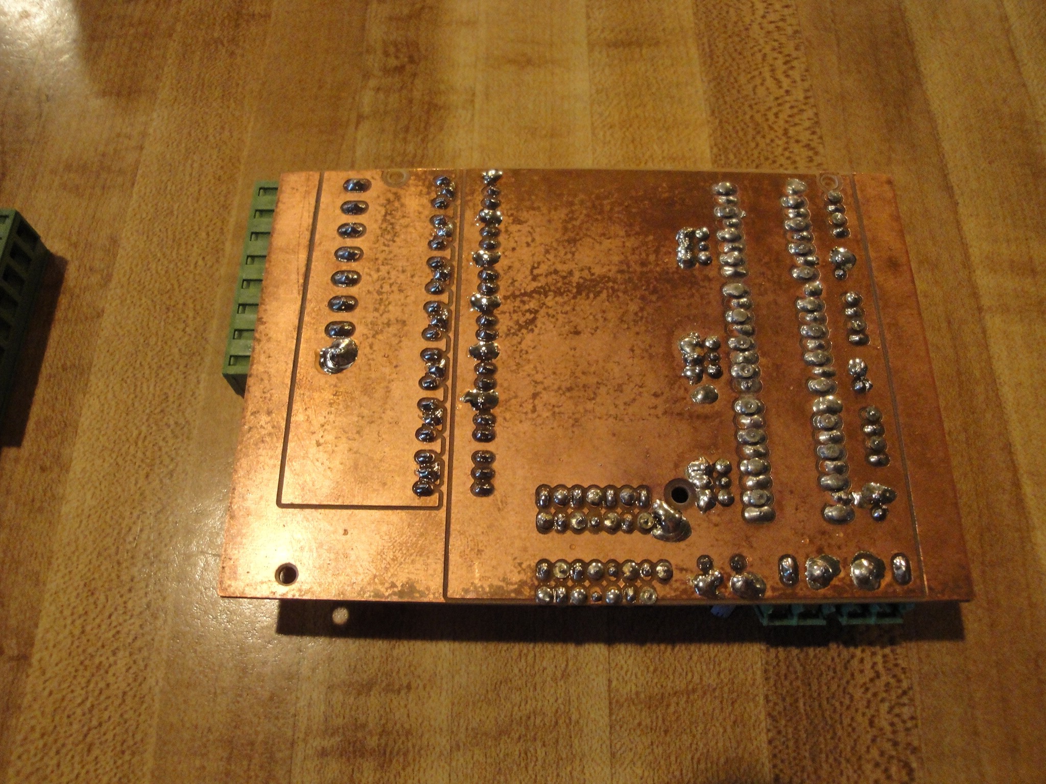
Now that the pcbs were machined, I then populated the boards. Solder jobs do not look the greatest, but continuity has tested ok. Here is the controller:
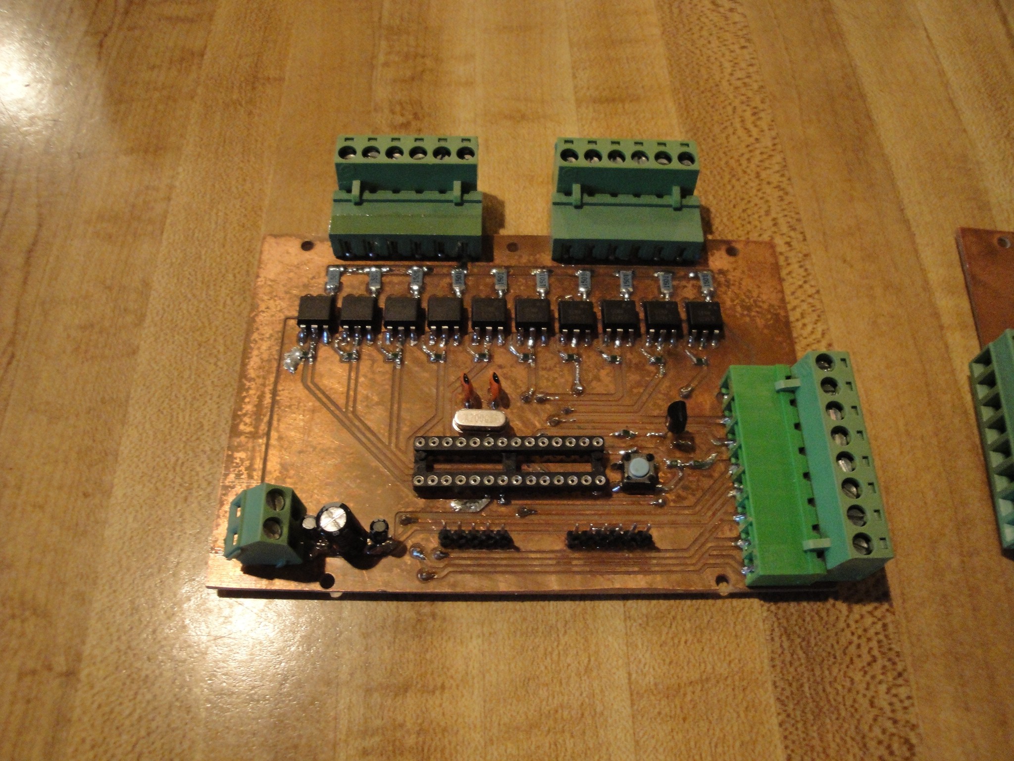
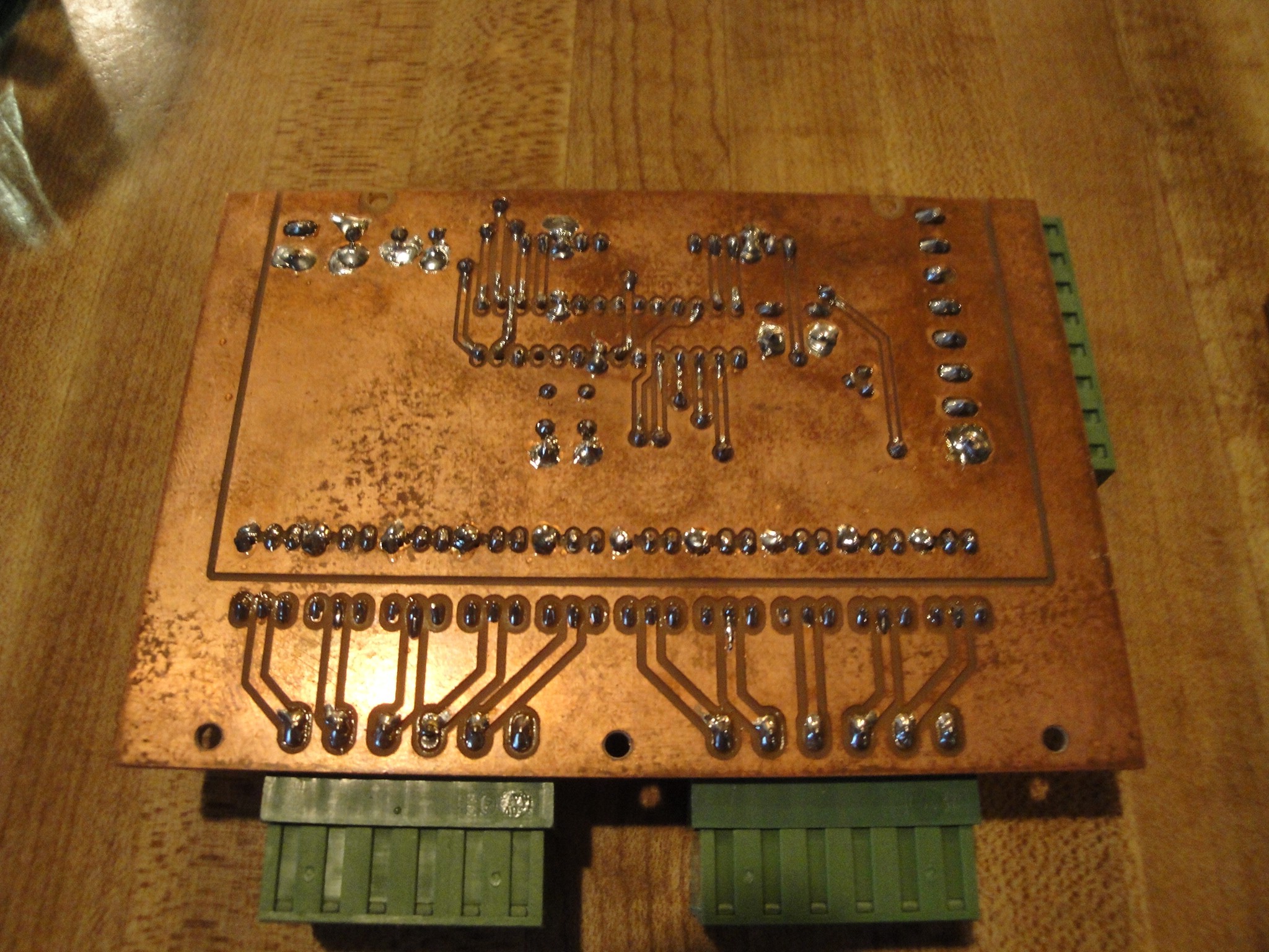
Here is the Driver board:
The next step will be to mount the boards inside of the computer case and finish wiring.
Discussions
Become a Hackaday.io Member
Create an account to leave a comment. Already have an account? Log In.