 James Ots
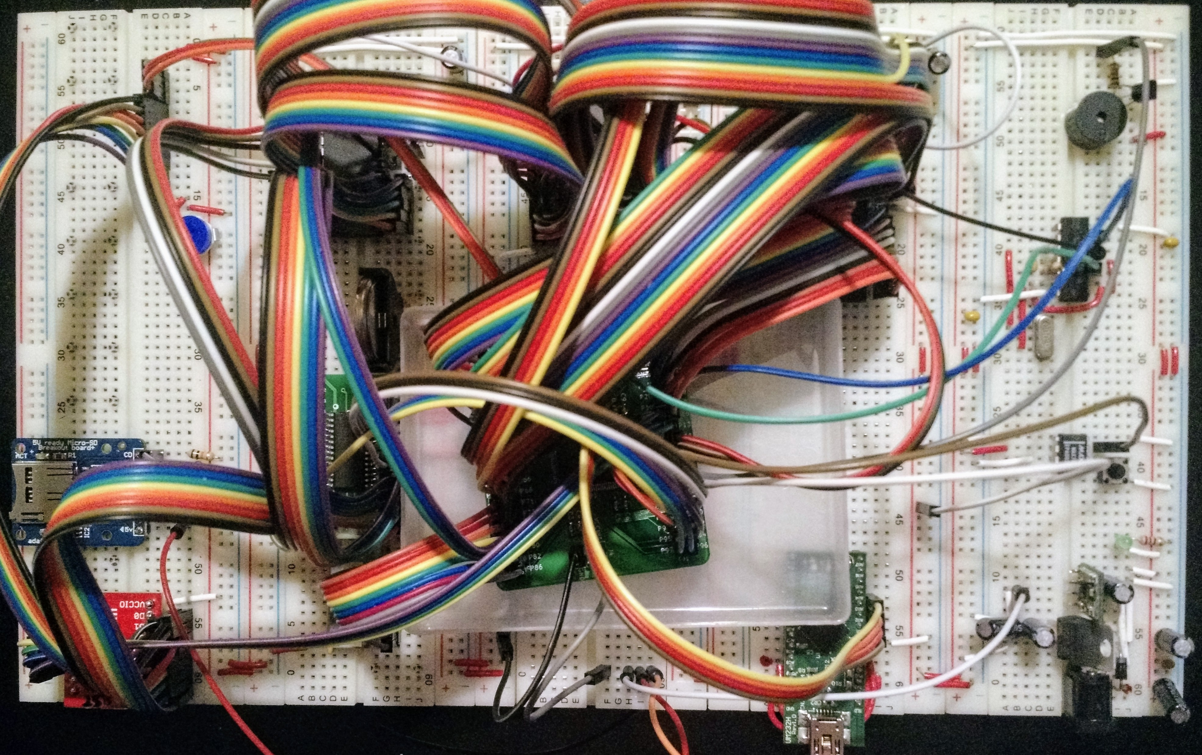
I've got everything wired up on the new board. I reorganised it a little so that both the USB ports and the power are all on the same side. The buzzer has been moved over to the right will all the other small components. The RTC has been moved over to the left so that the address and data busses have a more sane route around the board.
And it didn't work. After a long time checking things I discovered two problems. The RD and WR lines on the FTDI were swapped, and one of the wires on the clock was bent up underneath itself and then into the wrong hole so that it was almost impossible to see that it was miswired.
After I fixed these problems and slowed the clock down in the CPLD I was able to make it flash an LED on and off, so I knew that I'd at least got the clock working. But it was still failing to read from the FTDI.
And then everything stopped working, and all the LEDs went dim. I measured the voltages, and the 5V and 3.3V lines were reading about 3V and 2V respectively, and the 3V regulator was really hot. I switched off the power, and reaslised that the CPLD board's pins were touching the power links which this board has halfway down each side, which the previous board didn't need. I think I may have blown up the CPLD board, so I switched it out for my spare one and put it in a plastic tray this time. I also switched out most of the other chips I have, just in case.
I then wrote a CPLD configuration which is effectively Thomas Sherrer's minimal Z80 tester and switched the power on. The address lines are succesfully counting, so I now know I have a working Z80. Then I plugged in a USB cable and the lights all went dim again. But this time, after switching the power off and on again then everything was working fine. So I'm wondering if I've managed to partially destroy a power regulator. The shutdown line of the 5V regulator was unconnected, which is apparently okay, but I've now tied it to Vin just to be sure. And I've disconnected the screen as I wasn't sure if it was causing problems. I think I'll have to get a replacement 5V regulator as well — I've already changed the 3.3V one as I had a bunch of spares.
I also measured the current from each regulator — 300mA are being drawn from the 3.3V one, and 400mA from the 5V one (which includes the 300mA from the 3.3V regulator). Which would suggest there's probably no wiring problem at the moment. The 3.3V regulator does seem to be getting hotter than it did on the old board, although I might be misremembering that.
Discussions
Become a Hackaday.io Member
Create an account to leave a comment. Already have an account? Log In.