 Hexastorm
Rotating polygon laser scanners need to keep track of the angular position of the
prism or mirror.
In an earlier version of Hexastorm, this was achieved with a Sharp A160 polygon
motor. This board has a NIBC3111 chip. Motor speed could be
controlled by sending a PWM signal to this chip.
Using Hall sensors,
the internal circuitry of the board was able to stabilize the rotor
speed.
I added, a photo-diode and FPGA to accurately track the prism position.
The current approach
has several limitations;
- the control
algorithm is not open-source and hard to port to the PCB motor
- the performance
improvement by the photo-diode is not known,
the design
would be much more compact without photo-diode and just hall sensors
As a result, I decided to develop a new control algorithm. Let's say I want the energy to be uniform within 10 percent. This implies the angular velocity must be constrained within a Mean Average Percentage Error (MAPE) of ten percent. I need to know the angular position of the rotor within a MAPE of 0.005 percent. If it is assumed the line length is 24 mm, and the angular speed is uniform (in reality it is not but close), the exposure accuracy is 24*(0.005/100)=1.2 microns. In my experiments so far, I used a speed of 2000-3000 RPM.
My experimental
setup has several constraints. I don’t uses a micro-controller, so
I try to avoid divisions and multiplications in my control algorithm.
The hall sensors produce six states but these are not evenly spaced.
I already have a controller in place, which was implemented in 2022.
The current
controller first speeds up the rotor by flipping to the next state
after a given time.
This ensures the
rotor is rotating. Once rotation is established, the controller
switches to hall feedback mode. It simply enables the “right”
coils given the currently measured hall state.
Speed can be
measured by counting the time it takes to transition between 12
Hall states (i.e. 360 degrees).
The critical path is seen as follows;
1. Measure the speed of the rotor
There are 2x6 states in one rotation. If the new hall sensor state is not equal to the old hall sensor state. The old hall sensor state is updated AND one count is added to the number of states seen. If the total is six, the counter is reset and its value represent the time for six states.
If the hall sensors are sampled at a "too high" frequency this results in a lot of noise.
It turned out to be key to divide the clock frequency from 12 MHz to 14kHz
2. Determine the distribution of the Hall States (finished)
There are 2x6 states in one rotation. The Hall state is determined a
thousand times. If it is assumed the distribution is uniform, the rotor should be 1/6 of the time in a given state.
However, the distribution is not uniform. The following is measured;
state degrees cumsum
1 33 33
2 30 63
3 37 100
4 9 108
5 45 162
6 18 180
These values are stable and the measurement is repeatable.
I therefore conclude that the discrete set [angle0, .... , angle5]
+ offset_angle, describes the actual position where the motor should be triggered.
I still don't know the offset angle. Note, that ideally the angle would be [30, 60, 180] degrees and offset is 0 degrees. The values I have are far from ideal for state 4 and 6.
My measurements imply;
- the rotor is not pulsed optimally at the moment (a lot of power is lost)
- the incorrect pulsing could result in noise (I do see my speed drifts over time).
It oscillates whereas I except speed would slow down due to heating of the motor, i.e.
not an oscillation.
3. Improve the virtual distribution of the Hall States (finished)
First let's run a counter which goes from 0 to a 180 and then goes back to 0.
I then determine 5000 times the angle which is computed.
If I bin my data in 6 buckets with the edges [0,30,60,90,120,150], I arrive at the following distribution (note that the total is one).
1 0.167
2 0.167
3 0.167
4 0.167
5 0.167
6 0.167
I determine the time required for six states. I use this to determine the time for one degree.
The time for one degree is the time for six states divided by 180.
I use the trick that a division can be interpreted as an addition of a series of right shifted values;
input*2^-a + input*2^-b + input*2^-c
ergo
1000.000/180 = (a>>8)+(a>>10)+(a>>11)+(a>>13)+(a>>14) (where a = 1000.000)
which is slightly smaller and has an error of 0.45 percent. An error of 0.08 degrees.
I then run a counter from 0 to a 180 degrees, and reset this counter when I get a new speed measurement. I add one degree if my time counter reaches the time for one degree.
This results in the following distribution.
1 0.18
2 0.167
3 0.167
4 0.165
5 0.164
6 0.155
Note that this distribution should be in sync with the motor states and is much better than the one from step 2. Ergo this should result in better pulses.
Still it is not perfect, and speed seems to be "slightly" underestimated. The distribution is skewed to 1
I can improve this by using the values from step 2. So IF I measure state 2, I set my angle counter to 63 degrees (i.e. cumsum).
This results in the following distribution
1 0.172
2 0.165
3 0.165
4 0.173
5 0.165
6 0.158
This brings me to my new hypothesis.
- the rotor can be pulses better using this new distribution
4. Verify New pulsing scheme is better (finished)
I tried the following formula for the hall sensor positions;
beta = -15
hall_degs = (np.array([0, 33, 63, 100, 108, 162])+beta+180)%180
Varying the beta from -15 to 30 has a big impact on the performance.
Motor power got better than the pure hall feedback mode or the motor would
not function at all.
Note that the negative angle indicates I have to switch on a specific motor state earlier
than expected.
If I look at source https://hackaday.io/project/167173-custom-bldc-motor-board-using-fpga/log/174271-featuring-v07. I read;
The key word here is dead time insertion. It essentially refers to the mosfets not being ideal switches and not turning on or off instantaneously, but with a certain delay.
This implies it would need to be varied with speed.
5. PID Controller (done)
Thorlabs provides a guide and brief explanation on tuning a PID controller.
The derivative term is seldom used in practice and that's why I use a PI controller.
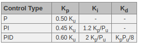
The Ziegler-Nichols method for PID tuning offers a bit more structured guide to setting PID values. Again, you’ll want to set the integral and derivative gain to zero. Increase the proportional gain until the circuit starts to oscillate. We will call this gain level Ku. The oscillation will have a period of Pu. Gains are for various control circuits are then given below in the chart.
An interactive example can be found here http://grauonline.de/alexwww/ardumower/pid/pid.html.
As Pu is hard to determine, the Ki can also be determined manually.
You should have an offset with P controller, it can not reach the set point as the error would be zero. This is fixed by the integral term.
The PID controller is implemented but not fully tuned.
6. Tune the controller (in progress)
Other topics:
Kalman filter
I briefly looked into Kalman filter. This could be used to increase the way the position and speed of the rotor is measured.
This is only done if it is needed.
In steady state, the speed is constant and our system is described with
the equations
Here p is position and v is velocity. With a Kalman filter, I could combine measurements to get a better estimate of the position and velocity, see source.
I foresee the following challenges;
- multiplications and divisions on a FPGA are complex (this seems required by the
Kalman filter)
- The measurement error is probably not Gaussian
As a result, Kalman filter theory might not apply.
My aim is to end up with a system in a very steady state. Rotor speed should be constant.
As a result, I would guess that even if Kalman theory applies. The Kalman gain should be constant.
So using Kalman theory for dummies, I simply assume where Kalman gain K is a constant, I could try to figure out the best Kalman gain by simply trying some values and seeing what works best.
Discussions
Become a Hackaday.io Member
Create an account to leave a comment. Already have an account? Log In.
The PID controller seems better than what I have https://hackaday.io/project/167173-custom-bldc-motor-board-using-fpga/log/174271-featuring-v07.
The way he measures the angular position seems different and I don't see a kalman filter.
Are you sure? yes | no
I doubt anything is perfect for what you have planned but I believe that building off something that exists is advantageous compared to implementing from theory alone. At the very least, it can give you a better idea of how to (or how not to) structure the code.
As for the Kalman filter, check out some of the myriad of verified FPGA implementations for which there are research papers as well as filter variations that may be better suited.
The general idea of this post is that the wheel that has been reinvented many times so you should take advantage of it if you can. Also, if nothing you find is suitable and you invent a slightly different wheel then perhaps a research paper is in order.
Are you sure? yes | no
Thanks, I made one crucial improvement. I over sampled my hall sensor, this led to the propagation of a lot of noise. So i lowered my sampling rate from 12 MHz to 14 kHz.
Are you sure? yes | no
Just FYI, if you decide to go the full implementation route in the future then this would be a good start: https://hackaday.io/project/167173-custom-bldc-motor-board-using-fpga
Are you sure? yes | no