 Michel Kuenemann
The battery box has got several features that are worth to be mentioned.
(Sorry for the annoying dashes in some comments. It's the only way I found to get a good aspect for the pictures...)
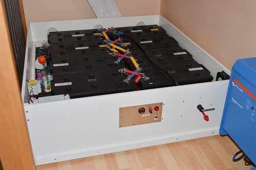
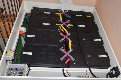
| General View | Close up on the 8 batteries |
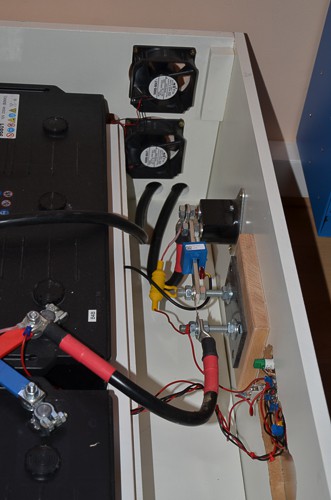
| The battery box contains 12V / 230Ah semi stationnary lead acid batteries. The 8 batteries are grouped 2 by 2 in parallel. 4 groups of 2 are connected in series. This constitutes a "2S4P" pack of 48 V / 460 Ah . It can provide 23 KWh at 50 % of depth of discharge. The battery box weighs approximately 500 Kg. The battery pack is located very close to the converter in order to minimize cable losses. | The green surface on the left side of the battery is a Polyethylene liner. This liner protects the wooden floor against a leak of acid that would be catastrophic otherwise. ---------------------------------------------------------------------------------------------------------------------------------------------------------------------------------------------------------------------------------------------------------------------------------------------------------------------------------------- |
 |  |
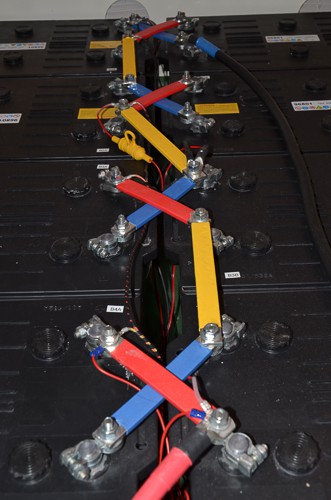
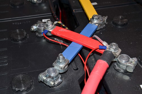
| Batteries interconnect | Connection detail |
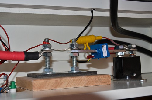
| The current flowing through the battery pack may reach up to 200 A. In order to minimize losses, the battery are interconnected by the means of short solid copper bars. The cross section of these bars is 120 mm². This yields a current density of less than 2 A/mm² in the worst case. The bars are tinned to avoid corrosion and insulated with thermo-retractable sleeve. The light gage wires are for voltage measurement. | The cable to the inverter has a cross section of 95 mm². --------------------------------------------------------------------------------------------------------------------------------------------------------------------------------------------------------------------------------------------------------------------------------------------------------------------------------------------------------------------------------------------------------- |
 |  |
| Front of the box | |
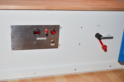
| When the battery voltage reaches 56 Volts, bubbles of hydrogen and oxygen come out of the batteries. 2 powerful fans eventually blow these gases out of the box. | This close up shows (left to right) the 200 A fuse, the current transducer (blue box) and the power switch (black box on the right). The current sensor is placed across a copper bar. |
 |  |
| Front panel equipment | |
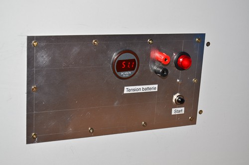
| The big lever on the right is the battery power switch. This lever is put on the "Off" position only during maintenance. ------------------------------------------------------------------------------------------------------------------------------------------------------------------------------------------------------------------------------------------------------------------------------------------------------------------------------------------------------------------------------------------------------------------------------------------------- | The basic "dashboard" comprises a digital voltmeter, a pair of banana plugs for an external voltmeter, an LED indicator and a "Start" push button. During system start-up this button allows slow charging of the converter's input capacitors (33 000 µF) through a resistor before turning the power switch on. Otherwise the huge current inrush could make these capacitors explode. (it happened once in the beginning ;-(). |
 |  |
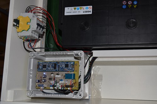
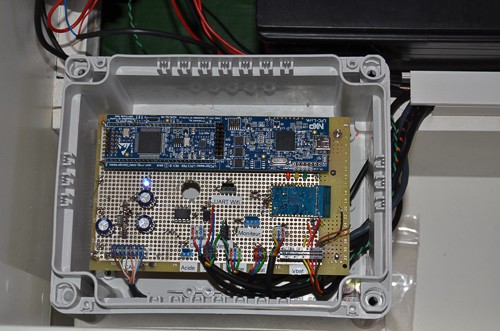
| The Battery Management System | |
| The management of the battery is one of the most demanding task in an autonomous PV System. This Battery Management System is based on an NXP Cortex M3 32 bit Microcontroller board equipped with a powerfull LPC1769 chip running at 120 MHz. The circuit breakers located on the left manage redounded +24 V DC distribution to supply the electronic boards. | The Battery Management System has following features :
---------------------------------------------------------------------------------------------------------------------------------------------------------------------------------------------------------------------------------------------------------------------------------------------------------------------------------------- |
 |  |
Discussions
Become a Hackaday.io Member
Create an account to leave a comment. Already have an account? Log In.