A little more work went into building the master box, but not that much.
Here is the schematic to the master box :
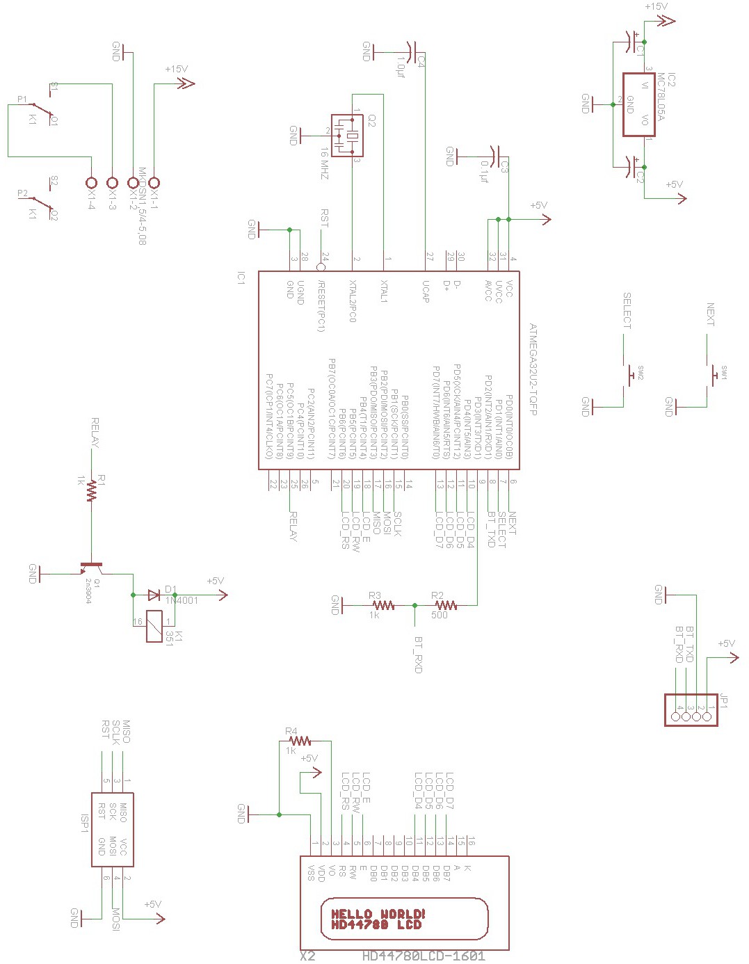
This circuit is very simple. 7 lines control the LCD , in 4 bit mode. There are 4 data lines and 3 control lines. Pin 3 of the LCD is connected to a 1k resistor to ground to set the contrast. There are 2 switches to manipulate the master box. Switch 1 is used to enter the settings mode, where you can change the PIN to unlock the door. It is also used to switch between options inside settings. Switch 2 is used to select the displayed option. Both switches are pulled up internally so they only need to be closed to ground to change state. The Bluetooth module's TXD pin is connected directly to the MCU and the RXD goes through a resistor bridge to lower the voltage to 3.3v towards the Bluetooth module. Port C pin 5 drives the relay that simulates pressing the button on the intercom. RST, SCLK, MOSI , MISO are needed for the AVR ISP connection along with a connection to ground, and power to the AVR. A 5v voltage regulator drops the 15v coming from the intercom to 5v and is filtered with a 1µf at the input and output of the regulator.
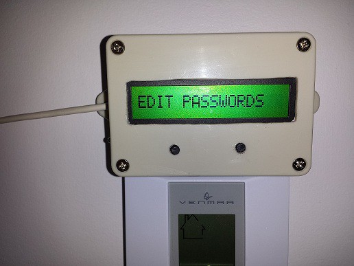
Fitting the LCD was tight, but it turned out perfect. Using my dremel I cut the plastic but sadly I went to close to the side, bottom right and I went through the plastic. So I decided that's where the power switch would go. I drill 2 holes for the switches and cut a piece of toothpick to help glue them more solidly with super glue.
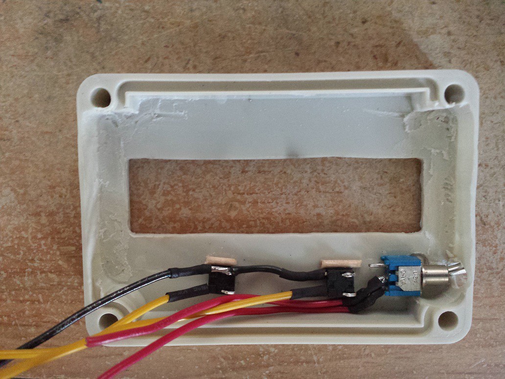
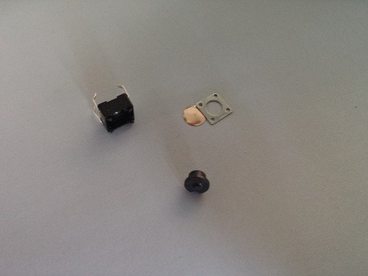
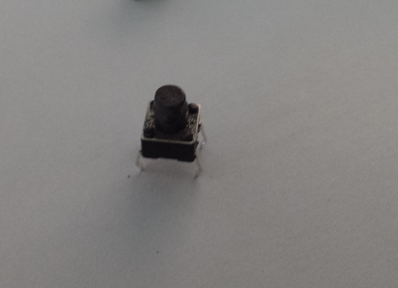
Both switches are grounded on one side , and connected to their respective pad on the board. The buttons for the switches were too short to come out the other side of the box. So I cheated and destroyed 2 extra switches and took the buttons, sanded the excess and glued them on top of the switches to make them taller :
This board turned out much cleaner than the slave keypad board, but this was also a different board that wasn't as old as the one used for the keypad. Here is a shot during the etching process using muriatic acid :
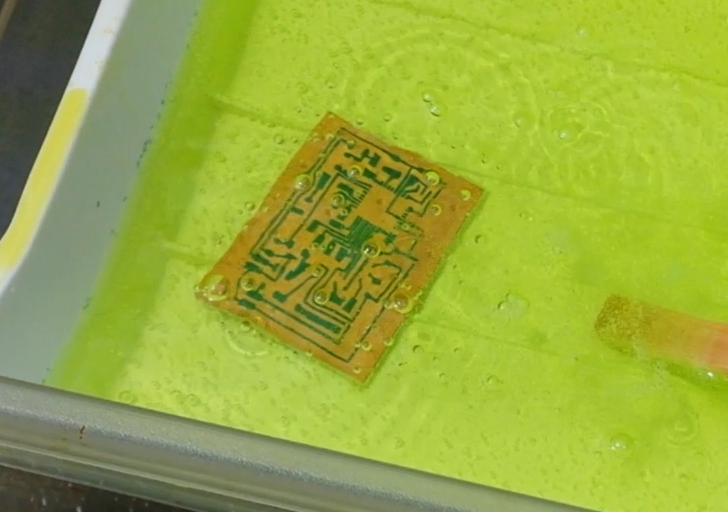
You should do this outside! There are a lot of fumes and your girlfriend might not enjoy the smell it leaves in the washroom once you are done.
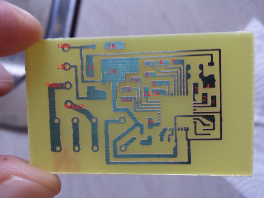
- Switch 1 is 1 and 16.
- Switch 2 is 2 and 16.
- Bluetooth is 5v: 17 GND : 16 RXD : 4 TXD : 3
- LCD is : E: 12 RW : 13 RS : 14 D4: 5 D5: 6 D6 : 7 D7 : 8 5v : 17 GND : 16 CONTRAST : 18
- AVR ISP : SCLK : 9 MOSI : 10 MISO : 11 RESET : 15 GND : 16 5v : 17
- GND is connected to the ground of the 15v regulator inside the intercom.
- 15v is also connected to the 15v regulator of the intercom.
- Relay 1 and 2 are connected directly to the switch that is pushed on the intercom when you want to unlock the door.
I forgot to take pictures just after populating the board, so here are some take once everything is wired :
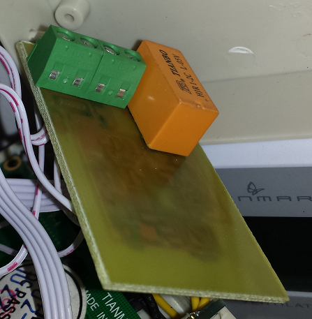
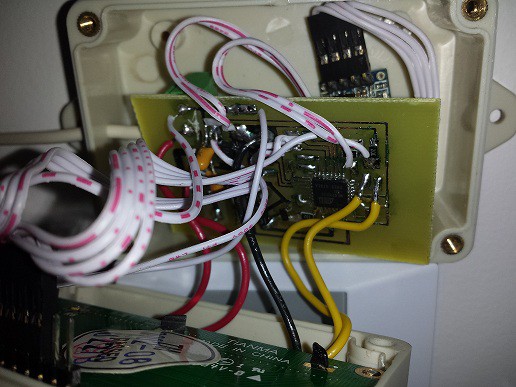
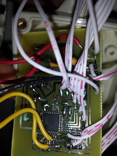
I used a 4 wire telephone cable connected to the phoenix connector inside the master box and soldered directly inside the phone :
Discussions
Become a Hackaday.io Member
Create an account to leave a comment. Already have an account? Log In.