 Jac Goudsmit
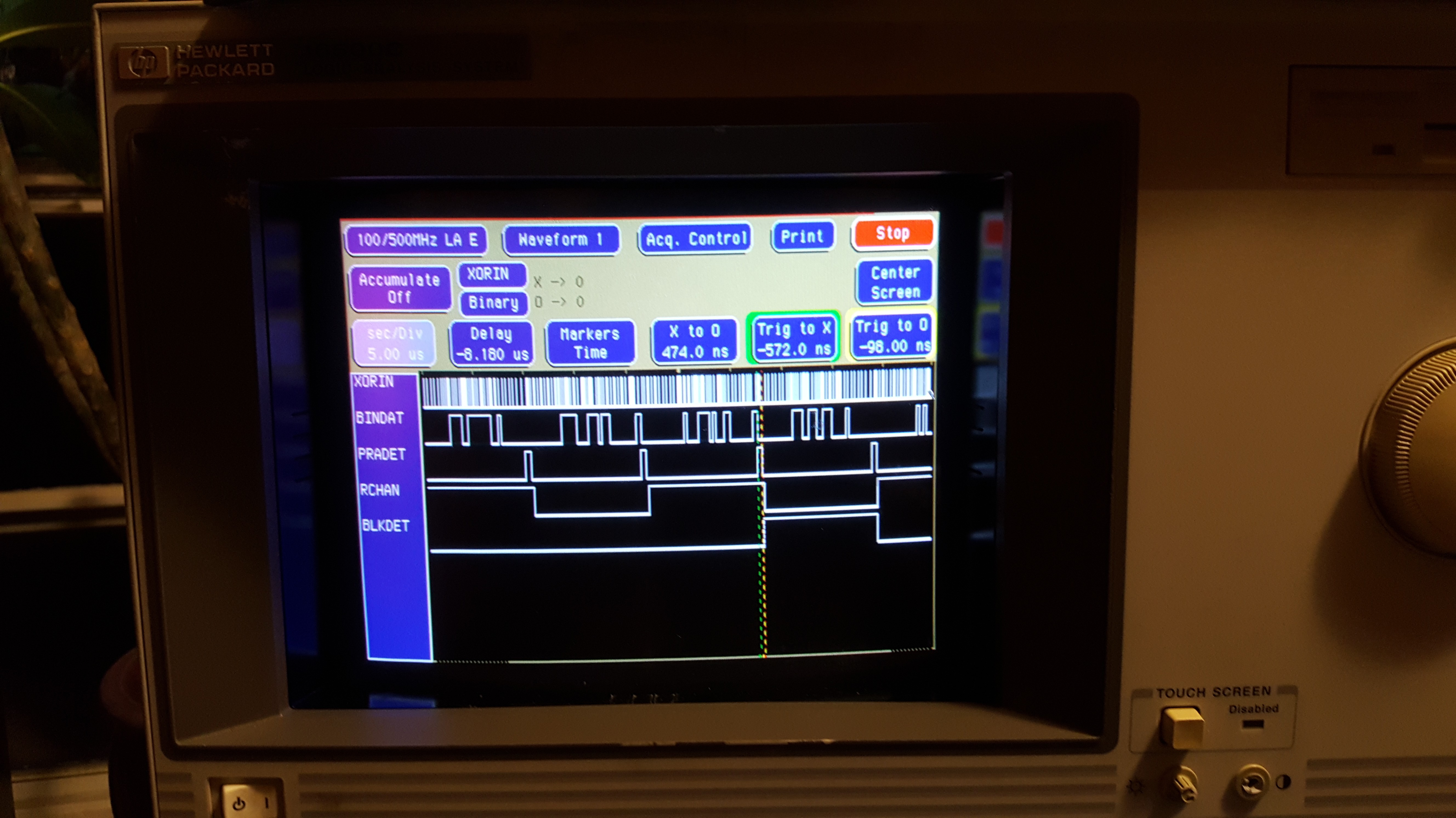
The idea that I presented in my previous log, to count pulses (instead of measuring time between pulses, or sampling for a second pulse in the middle of a bit) works great!
The Biphase Decoder now consists of two cogs that take care of all the following:
- Decoding the biphase bits in each subframe to regular binary values
- Detecting the preamble to detect the start and end of each subframe
- Decoding the preamble type to distinguish left and right channel samples
- Decoding the preamble type to distinguish the first subframe of a block from all the other subframes
- Storing a LONG word into the hub with all the information above, at the end of each subframe.
That took quite a few smart tricks with Propeller Assembler (PASM). For example I found out that it was more efficient to set the channel output pin to 1 for the left channel and 0 for the right channel instead of the other way around, and I found out that it was more efficient to decode the biphase bits in one's complement.
Let's have a look at some of the important parts of the code; for the full story, check out the source code on Github. The file biphasedec.spin has a lot of documentation at the top.
Two Cogs to Decode Biphase
When I started on writing code to count pulses instead of measure time intervals, I thought it might be possible to detect preambles in the same cog as the biphase decoder. I quickly discovered this was going to be very difficult or impossible. It's much easier to just leave the preamble decoding to a separate cog. So now there are two cooperating cogs: the Biphase Decoder cog and the Preamble Detector cog.

As a reminder, the XORIN input is produced by a small circuit that combines the S/PDIF input with a slightly delayed version of itself with an XOR port (see the diagram above, schematics are in previous log entries and in the source code).
The Biphase decoder decodes the bits by letting a timer count pulses on the XORIN input while the code stays in sync with the bit clock: There's always at least one pulse per bit, but there are two pulses for all bits whose value is "1".
The Preamble Detector uses a timer in NCO mode (Numerically Controlled Oscillator) to detect preambles. The timer is configured to make the PRADET pin go high when a long pulse (characteristic for preambles) comes in, and the code resets the timer at the beginning of each bit, unless the timer went off already. When a preamble is detected, the Preamble Detector decodes the type of the preamble. Then it reconfigures the timer again so that the PRADET output will go low again just before the XORIN pulse that marks the end of the preamble. The detected preamble type is then encoded on two output pins: BLKDET (BLocK DETect) and LCHAN (Left CHANnel).
The Biphase decoder tests whether the PRADET (PReAmble DETECT) pin is high when it starts processing a bit. If so, it "knows" that it's done with the entire subframe, and it stores the value in the hub. Then it waits for PRADET to go low again, which happens just before the beginning of the bit after the preamble (bit 4 of the subframe). Then it starts counting pulses again like before.
Biphase Decoder Cog
The following diagram illustrates the algorithm of the Biphase Decoder cog:
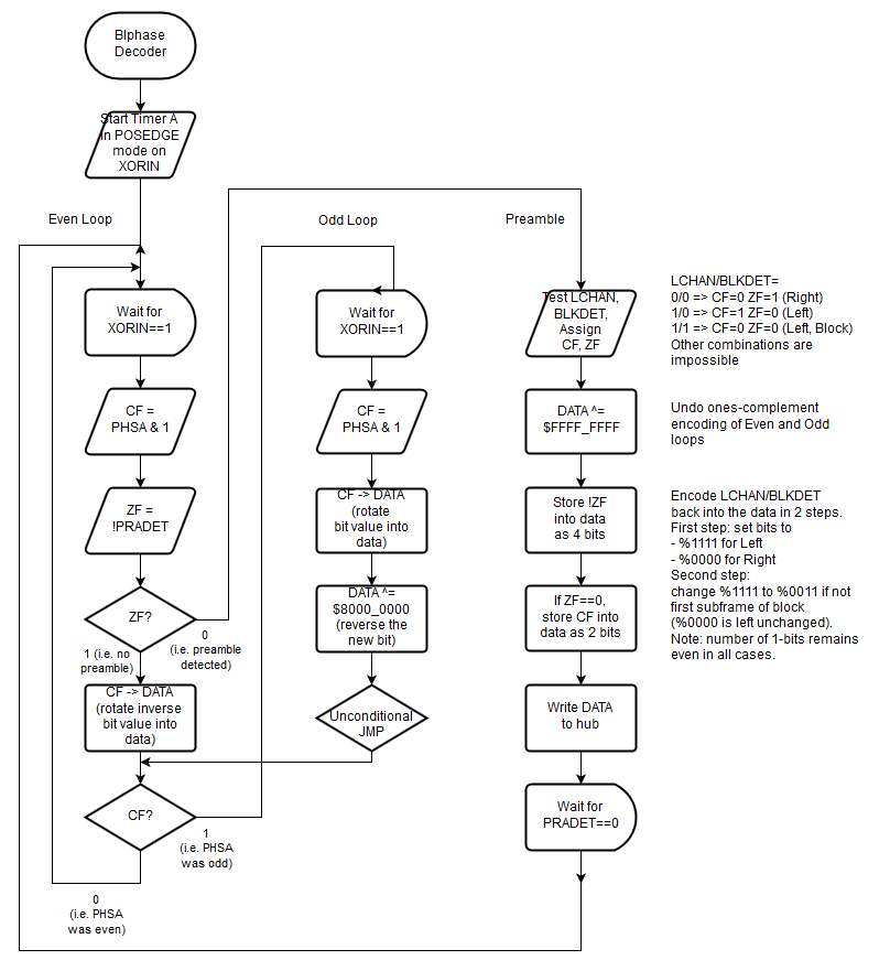
The Biphase cog sets up timer A of its cog to run in POSEDGE mode for the XORIN pin. That means that every Propeller clock cycle, the timer hardware checks if the XORIN input went from low to high, and if so, it increments register PHSA.
The code is designed to synchronize with the bit clock by executing 5 regular instructions of 4 Propeller clock cycles each, followed by a WAITPxx instruction which takes at least 6 clocks, to wait for a pulse on the XORIN input. Those instructions take a minimum of 26 clocks (325ns at 80MHz).
The purpose of the code is to test PHSA immediately after the WAITPxx instruction to see if the current count is even or odd. If the oddness changed since the previous bit, it means a 0 was encoded in the previous bit; if the oddness didn't change, it means there was an extra pulse, so a 1 must have been encoded.
Even Loop and Odd Loop
So the code needs to determine whether the value in PHSA went from odd to even, even to odd, even to even or odd to odd between the start of the previous bit and the start of the the current bit. It's easy to test for oddness by testing bit 0 of PHSA and storing the result in one of the flags, but there are no instructions to process one flag into another flag in a way that's useful for this.
So instead of storing the oddness, I wrote two loops: the Even Loop and the Odd Loop. The Even loop is executed when PHSA was even after the previous bit, the Odd loop is executed when PHSA was odd after the previous bit.
Both loops start by testing the new oddness of PHSA. If the count is odd, the Even loop should rotate a 0 into the result, whereas the Odd loop should rotates a 1 into the result. Then, depending on the new oddness, execution should jump to the Even loop or the Odd loop.
The Even Loop happens to be at the top of the code, so it can conditionally "fall through" to the Odd loop to save 4 clocks (because no JMP is needed). At the end of the Odd Loop, there is an unconditional JMP that jumps to the conditional JMP at at the end of the Even loop. This way, the number of executed instructions in the Odd Loop is identical to the number of the Even Loop, regardless of the current oddness of PHSA.
"Borrowing Time"
The Biphase decoder also tests whether the PRADET (PReAmble DETECT) pin (whose signal is generated by the Preamble Detector cog) goes high. When that happens, it jumps to the preamble code to store the value in the hub (see below).
There's a problem with this: The code uses the Carry flag to check the oddness of PHSA so that it can use the RCR (Rotate with Carry Right) instruction to store the decoded bit into the data that will eventually be stored in the hub, but the Even loop would need to store a "1" when CF=0 and a "0" when CF=1, and there's no time to add an extra instruction to invert the bit in the Even Loop.
On the other hand, the Odd loop doesn't have to do the test for the preamble, so though it has the extra JMP (to ensure that execution time is always the same), there is time in the Odd loop to reverse the bit after it gets rotated into the result data longword.
This made the solution very simple: keep track of the result data in one's complement. The Even loop doesn't have to reverse the Carry flag that way, and the extra instruction to invert the bit after shifting the Carry in, can be in the Odd Loop. When the code processes a preamble, it can reverse the data again before posting it to the hub.
Preamble Detection
The Even Loop checks the PRADET pin to check if a preamble is coming in. If so, it jumps to a separate section that encodes the detected preamble type and stores the result in the hub as a long.
PRADET is activated just before the end of the first long pulse of a preamble (see the Preamble Detector Cog section below). It goes low again just before the start of the first bit after the preamble. The Even Loop doesn't detect the preamble until the first XORIN pulse inside the preamble occurs, and then it has to get all its processing done before the end of the preamble, which is 814 ns later (worst case). Let's see how the preamble code in the Biphase Decoder cog has just enough time to get its work done.
- The Biphase decoder cog has 814ns from the first pulse in the preamble to the end of the preamble. That's 65 Propeller clocks (at 80MHz).
- It takes 3 instructions (3*4=12 Propeller cycles) to get from the Even Loop into the actual Preamble processing code. That leaves 65-12=53 clocks.
- The code needs to undo the one's complement encoding of the data, and encode the channel and the start-of-block flag into the result longword. We'll get back to this in a minute.
- Then it needs to post the result longword into the hub. The WRLONG instruction to do this is a hub instruction, which may take anywhere between 8 and 23 Propeller clocks. That leaves 53-23=30 clocks.
- To synchronize with the bit clock again at the end of the preamble (and the beginning of bit 4 in the subframe), the preamble processing code falls through to the WAITPxx at the beginning of the Even Loop. But before it's safe to wait on XORIN again, we first have to make sure that PRADET is low. It's okay if we're too late to wait for PRADET to go low, as long as we're waiting for XORIN before the pulse at the beginning of bit 4 happens. Each WAITPxx instruction takes a minimum of 6 clocks, so that leaves 30-(2*6)=18 clocks.
The Preamble detector generates two signals on the Propeller external pins, so that the Biphase detector can decode them and encode them into the result longword quickly. One pin is used to indicate which audio channel the subframe is for, and one pin indicates that the subframe is the first in a block. We could encode these bits into the data with two TEST instructions and two MUX instructions but then we don't have time to XOR the data with $FFFF_FFFF to undo the fact that the Even Loop and Odd Loop store one's complement bits into the data.
In a previous setup, I encoded the the channel as Left=0 and Right=1. But it's actually more efficient to encode Left as 1 and Right as 0 because it makes it possible to test both signals on the INA port at the same time using the WC as well as WZ modifiers of the instruction (otherwise, two separate TEST instructions would have been needed to get a non-ambiguous result). With those two modifiers, the Zero flag gets set if the test result is zero, and the Carry flag gets set if there is an odd number of ones in the result. So depending on the two pins (whose signal is generated by the Preamble Detection cog), we get:
- ZF=0 and CF=0 if LCHAN high and BLKDET is high (Left, first in block)
- ZF=0 and CF=1 if LCHAN high and BLKDET is low (Left)
- ZF=1 and CF=0 if LCHAN low and BLKDET is low (Right)
- Any other combination is impossible.
The code encodes the channel and the block detection into the 4 bits of the result longword, two bits at a time so that the parity stays even.
It can use a simple MUXNZ (or MUXNZ) instruction to encode the channel into the longword, but to encode whether BLKDET was true or not, it has to do a conditional MUXC or MUXNC (otherwise it would look as if BLKDET is true for all right channel subframes as well as some left channel subframes. So to encode the BLKDET bits, it must use a conditional MUXC/MUXNC which would mean that the BLKDET bits would be undefined for the right channel because the instruction wouldn't be executed.
So the code sets the bits for the channel and BLKDET first, and the values of the bits are chosen such that the value for the right channel is equal to the value that stands for "no BLKDET". Then we can conditionally encode the BLKDET bits (again) to overwrite them if we're working on the left channel
So to encode the bits from the INA register (generated by the Preamble Detector cog), we need 3 instructions (one TEST followed by an unconditional MUX instruction and a conditional MUX instruction. So a total of 4 instructions (including the XOR to undo one's complement encoding) to finalize the data before posting to the hub. That leaves 2 clock pulses. So the preamble code in the Biphase Decoder cog is done right on time. Nice!
Preamble decoder
The Preamble decoder is in charge of detecting preambles in the first place, and making sense of the various preamble types.
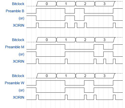
Every subframe starts with a preamble, and there are three possible types, all of which start with a long pulse.
- The B preamble indicates that the following subframe is for the left channel, and also marks the beginning of a 384 subframe block (which is important for subchannel decoding)
- The M preamble indicates that the following subframe is for the left channel but isn't the start of a block
- The W preamble indicates that the following subframe is for the right channel
The Preamble Detector cog uses the following algorithm:
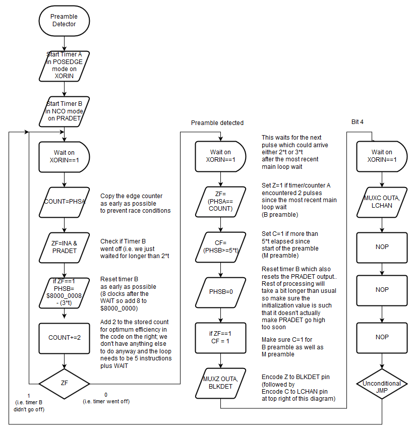
We use two timers to decode preambles:
- Timer A counts pulses on the XORIN input, just like timer A in the Biphase Decoder cog (each cog has two timers which can only be used by their own cog). We use this to distinguish between a B preamble and the other preambles, because the B preamble has two short pulses in the middle and the others don't.
- Timer B is used as an NCO timer that uses PRADET as output and is configured in such a way that it sets that output high after a little more time than 2*t (where t is the minimum pulse length that we have to deal with, which is the time that two pulses in a biphase encoded "1" bit are apart). We use this to detect the start of a preamble, and to distinguish between the M preamble and the other preambles, because the M preamble has a long pulse in the middle as well as at the start.
The Preamble detection code repeatedly waits for a pulse on XORIN to stay in sync with the bit clock, and executes 5 normal 4-cycle instructions in between to make sure that no false triggers happen, just like the Biphase Decoder cog. During normal incoming bits, the NCO timer doesn't go off before the end of the bit, so PRADET stays low. During each loop, the code resets the timer unless it already went off. It also stores the pulse count increased by 2. This code repeats itself unless the NCO timer went off.
All of the above happens after the end of the first long pulse, and takes exactly 5 instructions. The code then does a WAITPxx to wait for the next pulse.
- For B preambles, this happens after the two short (1*t each) pulses in the middle of the preamble
- For M preambles, this happens after the long pulse (3*t) pulse in the middle of the preamble
- For W preambles, this happens after the single short (2*t) pulse in the middle of the preamble
So to decode the preamble, the code checks the counter against the previous counter value plus 2, and it compares the elapsed time in the NCO phase register against a known value. Depending on the results, the LCHAN pin is set to 1 for B or M preambles, and the BLKDET pin is set to 1 for B preambles.
Generating the BLKDET and LCHAN outputs takes just a little too long to be done before the preamble is over. So while it's processing the above, the code resets the NCO timer to make PRADET go low. At that time the Biphase decoder knows that the preamble is almost over and it's time to wait for the next bit pulse for the start of bit 4. But the Preamble Detector cog still has to do some work, including putting one of the flags onto an output pin. It's not a problem that the BLKDET and LCHAN pins get updated so late because the pins aren't probed until the end of the subframe.
Conclusion
The code now contains enough functionality to decode the biphase data and store each subframe (with additional bits set for the channel and for block markers) in the hub at a specific location. But the location never changes, so any code that wants to use the data probably has to be written in PASM just to keep up.
I tried an experiment to change the Biphase Decoder cog so that it stores the subframes in an array of 384 longs (one block), but it takes too many instructions to get it done before the end of the preamble. However, the good news is that it doesn't need to be done by the end of the preamble!
The Biphase Decoder cog is basically always one bit behind, and while bit 4 (the first bit right after the preamble) is arriving, the code basically tries to decode bit 3 which doesn't actually exist: because of the way we store our state, it always decodes bit 3 as zero, but that doesn't even matter: once the Biphase Decoder encodes the BLKDET and LCHAN signals into the longword, bit 3 gets overwritten anyway.
That's a waste of time. So the plan is to modify the Preamble detector cog to turn the PRADET signal off a little later: not before the start of the first bit, but before the end of the first bit. That gives the Biphase Decoder cog enoug extra time to update pointers, buffers and counters to fill a buffer with subframes.
The Preamble detector cog doesn't have a whole lot to do while there's no preamble to decode. But it does need a carefully crafted timing constant. I'm thinking of trying to add code to that cog to automatically determine the timing constants while it's not time to decode preambles yet.
But I'm also thinking I should write some demonstration code based on what I have now. A VU meter cog that works with LEDs on output pins, or maybe a PWM based DA converter that plays the digital data to a speaker through a single pin.
We'll see.
Discussions
Become a Hackaday.io Member
Create an account to leave a comment. Already have an account? Log In.