 Max.K
Max.KThe goal for this project was to build a small robot which could be controlled wirelessly with video feed being sent back to the user. Most of my previous projects involved Arduinos but while they are quite capable and easy to program, there are a lot of limitations with simple microcontrollers when it comes to processing power. Especially when a camera is involved, there is now way around a Raspberry Pi. The Raspberry Pi Zero W is the ideal hardware for a project like this: It is cheap, small, has built in Wifi and enough processing power and I/O ports.
Because I had barely ever worked with a Raspberry, I first had to find out how to program it and what software/language to use. Fortunately the Raspberry can be set up to work without ever needing to plug in a keyboard or Monitor and instead using a VNC connection to a remote computer. For this, the files on the boot partition of the SD card need to be modified to allow SSH access and to connect to a Wifi network without further configuration.
The next step was to get a local website running. This was surprisingly easy using Apache, which creates and hosts a sample page after installing it.
To control the robot, data would have to be sent back from the user to the Raspberry. After some failed attempts with Python I decided to use Node.js, which features a socket.io library. With the library it is rather easy to create a web socket, where data can be sent to and from the Pi. In this case it would be two values for speed and direction going to the Raspberry and some basic telemetry being sent back to the user to monitor e.g. the CPU temperature.
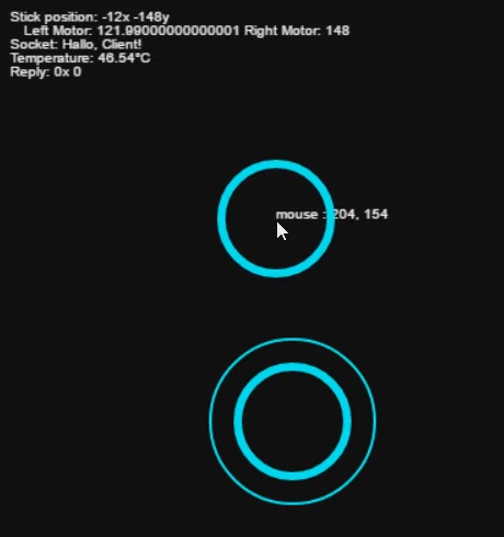
For the user interface I wanted to have a screen with just the camera image in the center and an analog control stick at the side of it. While searching the web I found this great javascript example by Seb Lee-Delisle: http://seb.ly/2011/04/multi-touch-game-controller-in-javascripthtml5-for-ipad/ which even works for multitouch devices. I modified it to work with a mouse as well and integrated the socket communication.
I first thought about using an Arduino for communicating with the motor controller, but this would have ruined the simplicity of the project. In fact, there is a nice Node.js library for accessing the I/O pins: https://www.npmjs.com/package/pigpio. I soldered four pins to the PWM motor controller by using the library, the motors would already turn from the javascript input.
After I finally got a camera adapter cable for the Pi Zero W, I started working on the stream. I used this tutorial to get the mjpg streamer running: https://www.youtube.com/watch?v=ix0ishA585o. The latency is surprisingly low at just 0.2-0.3s with a resolution of 640x480 pixels. The stream was then included in the existing HTML page.
With most of the software work done, I decided to make a quick prototype using an Asuro robot. This is a ancient robot kit from a time before the Arduino existed. I hooked up the motors to the controller and secured the rest of the parts with painters tape on the robot's chassis:
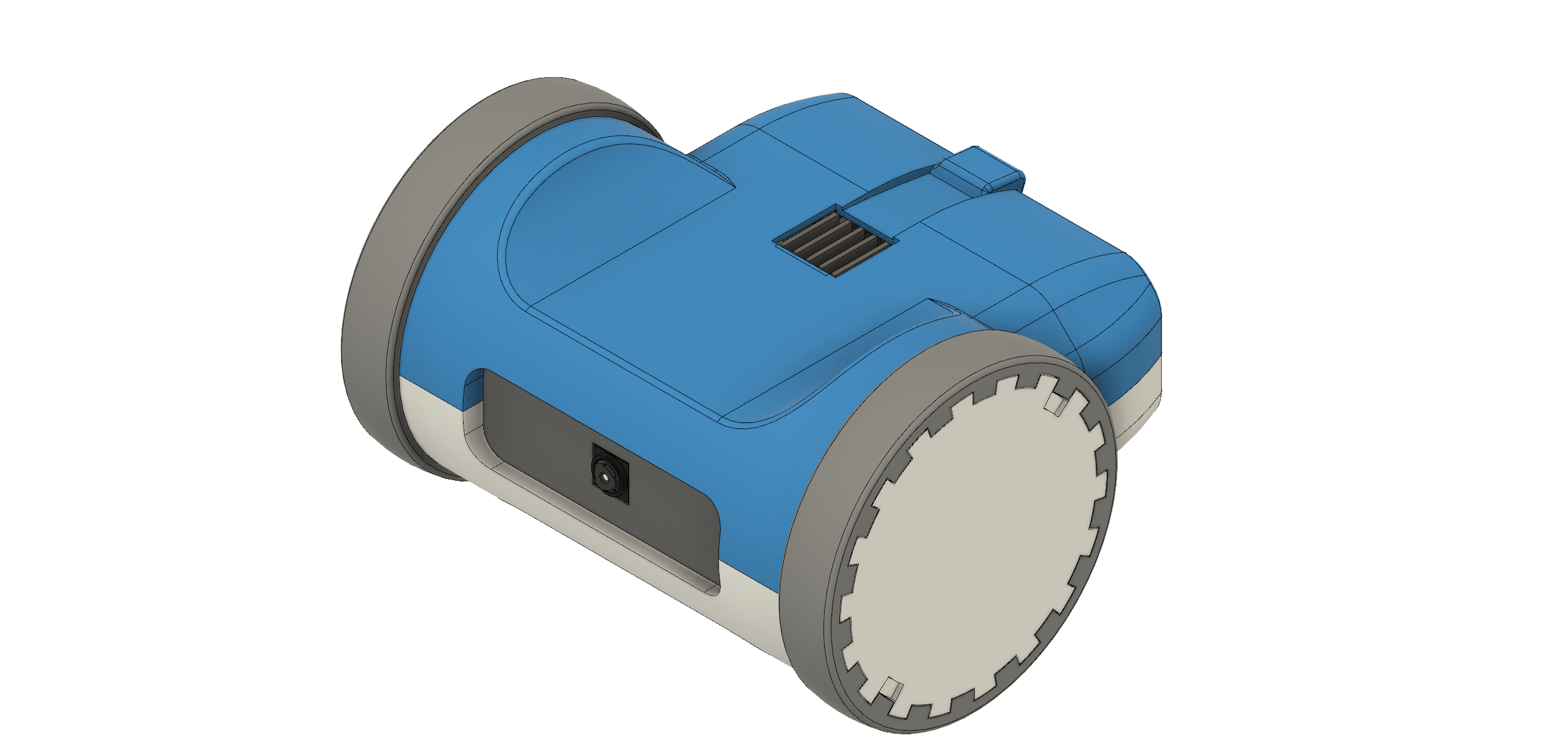
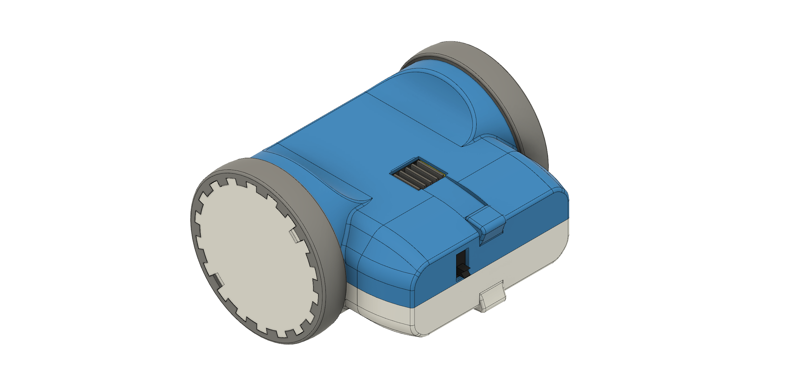
After the successful prototype I arranged the components in Fusion 360 to find a nice shape for the design. From my previous project (http://coretechrobotics.blogspot.com/2015/12/attiny-canbot.html) I knew that I would use a half-shell design again and make 3D printed parts.
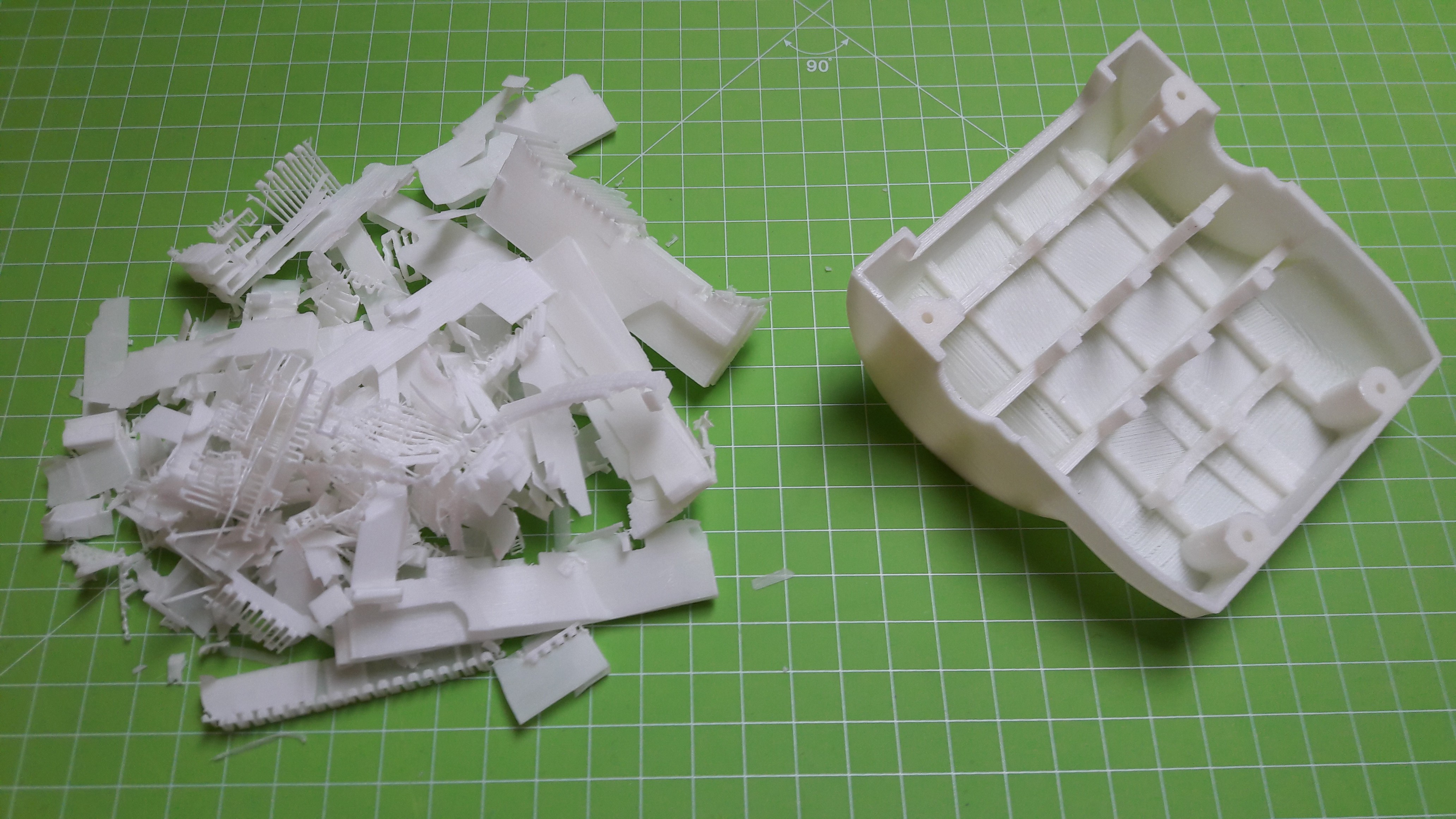
The parts were printed in regular PLA on my Prusa i3 Hephestos. The wheels are designed to have tires made with flexible filament (in my case Ninjaflex) for better grip. For printing the shells, support materia is necessary. Simplify3D worked well with this and made the supports easy to remove.
After printing the parts and doing some minor reworking, I assembled the robot. Most components are glued inside the housing. This may no be professional approach, but I wanted to avoid screws and tight tolerances. Only the two shells are connected with four hex socket screws. The corresponding nuts are glued in on the opposing shell. This makes it easily to access the internals of the robot.
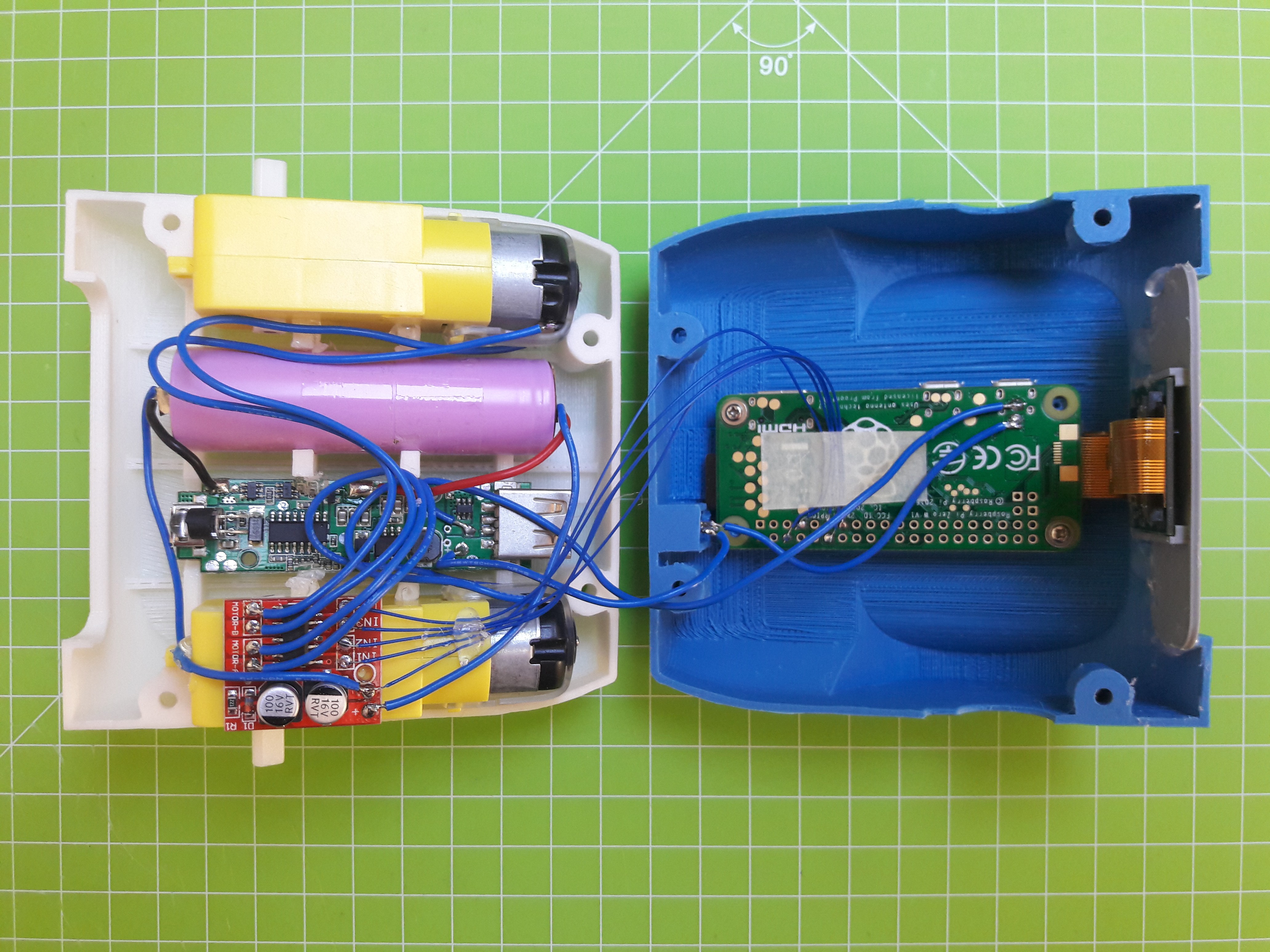
For powering the Motors and Raspberry, two separate power supplies/ batteries should be used to protect the Pi from overvoltage. I decided to take apart a power bank and attack the 3.7 V battery directly to the motor controller. The regulated 5 V from the power bank's board are fed into the Pi. So far, this works perfectly fine. The robot can be charged with a micro-USB cable from the inside. I might have to add a charging port later for better accessibility.
In a last step I configured the Raspberry to act as a Wifi Access Point using this script: https://gist.github.com/Lewiscowles1986/fecd4de0b45b2029c390. This way, the robot works anywhere and is not restricted by a Wifi router.
Discussions
Become a Hackaday.io Member
Create an account to leave a comment. Already have an account? Log In.
Good idea to configured the Raspberry to act as a Wifi Access Point. As this you can bring your zerobot anywhere and blowup your friends/colleagues ^_^
Are you sure? yes | no