 Simon Merrett
Having played around looking for the optimal sawtooth current pulse, my last log concluded we were aiming for 12-14mA peak, at the start of the pulse. I took this to LT Spice to see what pulse times would work with what inductor values and voltages to achieve this. Remember that in the next version (V1.1) of #Yapolamp we're planning to use supercapacitors to run the thing, so we are likely to see a large range of supply voltages. For now, I will say our planning range is 4.7V, the top charge I expect to get the capacitors to, to 1.8V, where the ATtiny will stop being reliable.
The first Beta Yapolamp uses 5 of the Chanzon 5730 LEDs in parallel (with that crazy "it shouldn't work" inductorless driver circuit). For some reason I think we'll be looking at 6 LEDs in total this time (more layout options) and I think we should try driving a 2 Series 3 Parallel arrangement. I'm not aware that there are any huge disadvantages of driving 2S 3P over 6P - your inductor needs to generate a larger pulse voltage to overcome 2x the forward voltage of your LED but the current is kept lower. Indeed, driving LEDs without individual current limiting on each circuit line is frowned upon, so moving to more LEDs in series is returning towards "good" practice, at least nominally.
So to start off this round of simulation, I will only use a pair of LEDs in 2S 1P configuration, with a 2.2mH inductor.
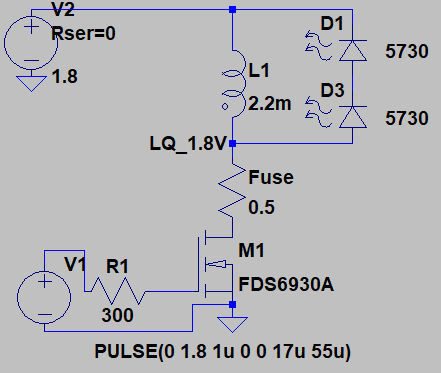
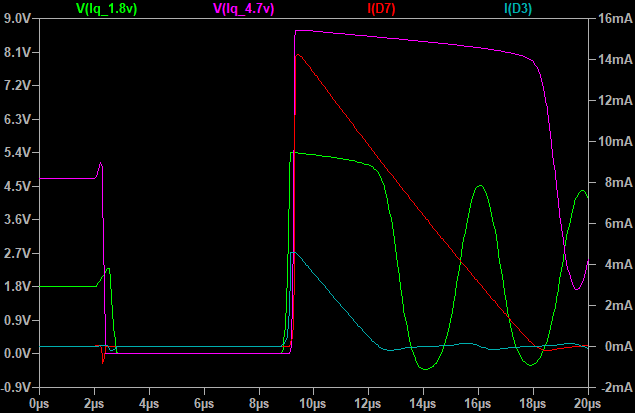
I want to see what the voltage range does to the peak sawtooth current. I found with a 4.7V supply (Vpulse is the same as the supply) and 6us pulse pulling the inductor to ground (pink trace), we get our 14mA (red trace) peak current. However, that same pulse length (green trace) at 1.8V supply only manages a measly 4mA (turquoise trace) peak current:
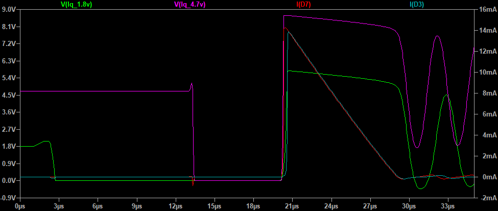
If I want to match them up, I need to give the 1.8V system a 17us pulse. Here's what that looks like against the 4.7V 6us pulse (delayed the 4.7V system pulse so the sawtooth discharge currents align):
Let's leave Spice there for now and just update on some of the playing I have done with the prototyping/test board. I have connected both the classic driver and the MT9284 sides as well as populating the supercapacitor chargin circuit. Here you can see the supercapacitors powering two LEDs through the classic driver with a 2.2mH inductor and a 3V pulse from an ESP8266.
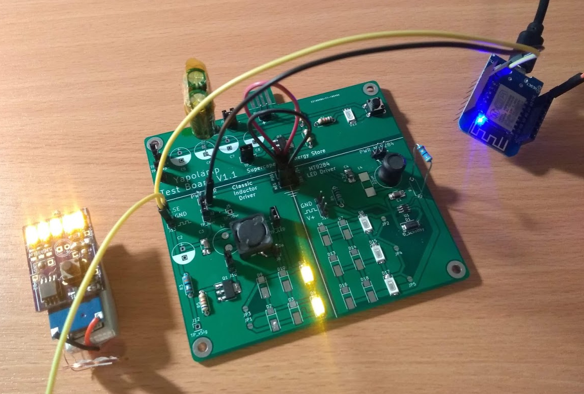
I'll do a more detailed log on the MT9284 another day but for now it gives me too many concerns to use with supercapacitors, due to it's ultrabright startup and then noticeable drop in brightness, audible whining and then very quick burn through the supercapacitor charge. I don't think I want to pair that IC with supercapacitors for now, although for more stable power sources it's definitely something I'd consider. It also cuts out at 2.2V and although that's not far from the cutoff voltage of 1.8V for the ATtiny that is likely to be driving pulses in the V1.1 Yapolamp, the classic driver has been putting light out down to below 0.5V on the capacitors! I admit I haven't completely ruled out the pulse input being significant in this observed performance (although there's a low value resistor in there). If it was a driver circuit that could light LEDs down to 1V, I don't know how I'm going to take advantage of that yet. It would be amazing to go into a distinct version of the always-on mode which told you that you need to charge the Yapolamp before you can use it in full mode. Could the microcontroller do high level management of it's a joule thief or charge pump for self operation down to those low voltages, say by kicking it in at 1.8V?
My first design flaw was to make this board for a single supercapacitor in series and several in parallel. That was silly because most of the supercapacitors I'll want to use will only be ~2.7V rated, so will need to be paired in series. For now I have twisted the legs of two capacitors together in the middle and taped them out of the way with kapton tape, before soldering the pair into the holes for one capacitor. They are 3F Cooper Bussman jobs. I can fetch part numbers if anyone is keen but I plan on using larger capacities in the full V1.1 design, as the pricing doesn't seem linear, run time is always in short supply with full brightness mode. With a totally unoptimised pulse regime of around 22us pulse on and 18 us pulse off, I'm getting about 5 - 10 minutes from a single pair of LEDs and a 3F capacitor battery. I think a couple of pairs of 10F 2.7V capacitors for an overall bank size of 20F would fit within the existing form-factor and provide good run time over 6 LEDs.
I have managed to charge the capacitors successfully several times from a USB battery pack, so the tab is good. It would need a shim or to be made on 2.0mm FR4 for the final version, in order to push the contacts together when inserted into the USB battery - 1.6mm is cheap but too thin for USB connectors.
One concern I have from the current charging circuit is that the supercapacitors appear to discharge even when well disconnected to other parts of the circuit, such as the LED drivers. I had the supercapacitors in a breadboard before and I know they don't self-discharge in a noticeable way like they are now. Any thoughts on what is causing this? Do Schottkys leak? Bear in mind I've observed this with J11 disconnected too...
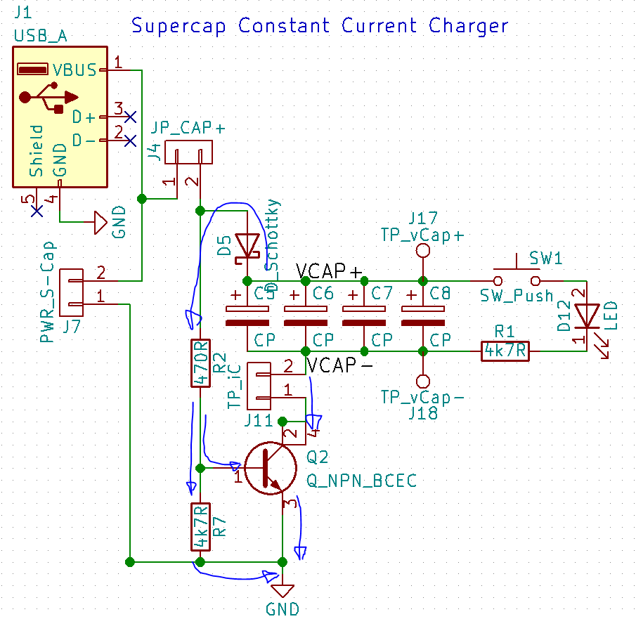 I'll finish up this log with some measurements from the oscilloscope at the connection between the inductor, MOSFET and LED. They look reassuringly similar to the Spice plots. Hooray!
 First up is "the curve I was aiming for". This is some time into the discharge, say 30 seconds to a minute and capacitor voltage will still have been more than 3V (sorry for the vagueness - was really poor at noting observations tonight)
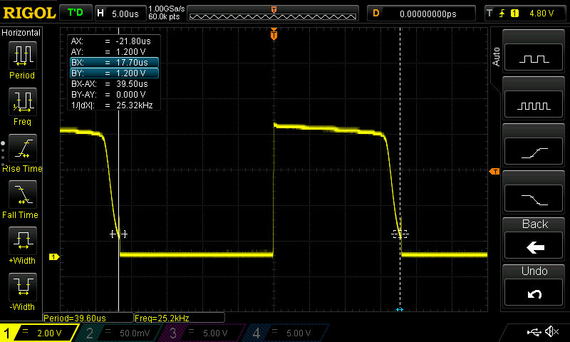
Next is what it looked like when I disconnected the USB battery that had been charging the capacitors. The inductor's discharge into the LEDs is cut short by the next pulse, which isn't what we want as this will be wasting energy in the inductor's magnetic fields that could have been converted to photons yet was cruelly "earth spiked" (note the different time base - all durations are the same length as before):
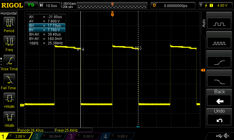 Finally here's what things look like when the capacitors have discharged down to about 1.8V but the pulse regime has remained the same:
Pretty sad but let's hope we can address all this with smarter pulse lengths in a future log. It's also lovely to see the oscilloscope trace resemble something you made in LT Spice. I'm starting to trust the tools more now!
Discussions
Become a Hackaday.io Member
Create an account to leave a comment. Already have an account? Log In.