 Simon Merrett
As predicted at the end of the last log, there were more mistakes learning opportunities with the latest version of the #Yapolamp. One of the tests I ran through was to connect the board to the power supply and ramp it up and down through the range of operating voltages I expect the system to see from the supercapacitors as they discharge.
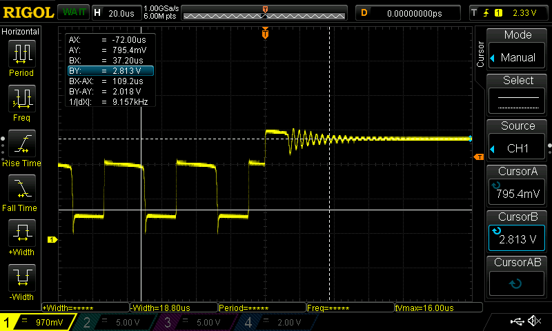
As I ramped up from 2.5V past 3.5V, I started to see strange behaviour. The system would work correctly in "always on" mode, the low power mode where the microcontroller sleeps and wakes periodically in order to quickly drive the LED, using the inductor and MOSFET, as normal. However, when I pressed the button to change modes, the "full on" mode would only stay on for a second or two before switching back down to the lower brightness "always on" mode. This also seemed to happen when the supply voltage went too low (around 2.2V if I recall correctly). Here's a scope trace of the feedback pin on the ATtiny402 at the moment it "gave up" and changed modes:
I went back and compared the circuit of my PCB design with the breadboarded version it was based on. The forward voltage on the feedback voltage dropping LED was the same, the voltage divider resistor values were the same. Very confusing. Next, I compared the waveforms of both PCB and breadboard versions at the feedback pin, to see if there was a significant difference. My hypothesis was that something was causing the feedback voltage to fail to reach logic level thresholds (see discussion and comments in earlier logs about whether the analogue comparator would have been a better way to trigger subsequent MOSFET pulses) and somehow I had got lucky in the magic formula of my feedback voltage dropper/divider on the breadboard version that was somehow unsuitable for the PCB version. Here are the two feedback traces running concurrently (blue is breadboard version, yellow is PCB version):
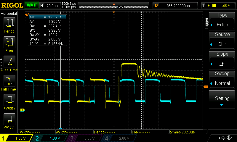
Well that blows my first hypothesis out of the water - the yellow trace is clearly spanning at least the same, if not a larger, range of voltages as the breadboard blue one. But there are some spiky edges to the PCB version trace - maybe that's part of the issue. I decided to hold a 1uF capacitor across the 10k ohm resistor that pulls the feedback pin to ground and for as long as I could reliably hold it in place, it seemed to sustain the "full on" mode for much longer (until my hand wobbled and I broke contact). So then I looked back at my green-wired PCB more carefully and in my haste/laziness noticed two unpopulated capacitor positions:
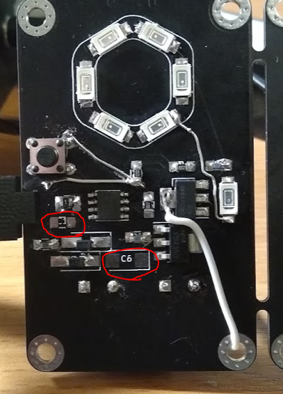
My next hypothesis was that all this inductor-ringing with no decoupling capacitor (C1) might be causing my poor ATtiny402 to be resetting, so I soldered two 100nF capacitors in C1 and C6. With both in place, I went back and ran the supply voltage sweep - happily, it now accepted 4.8V and maintained "full on" mode but sadly started having sporadic black outs below about 2V.
This got me thinking about what the differences between the breadboard version and the PCB version. So I looked more closely at the breadboard version and noticed I had soldered a 4.7uF cap between the inductor and ground! I also registered that there is now a PTC resettable fuse in series between the supercapacitors and the inductor, which will introduce a few ohms of resistance. There's a chance that the instantaneous current draw when the MOSFET closes is causing heating/tripping issues with the PTC and that a larger capacitor (than the first 100nF) at C6 might help. So I swapped C6 for the same 4.7uF capacitor as on the breadboard and here's what the new feedback trace looks like:
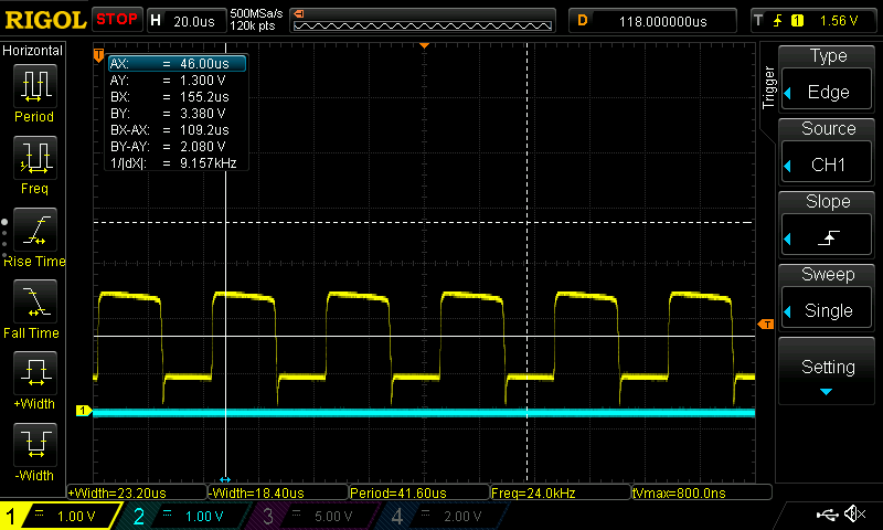
The high spikes are definitely gone but the low trough spikes remain - but now I think the PTC "choking" current and C6 absence value are more likely what was causing issues. The black outs are now only apparent at 1.8V and because this is the voltage at which I want the user to recharge the torch, it's not a bad behaviour as it would visually prompt a recharge. I'm confident that with a slightly larger value at C6, this behaviour will not appear at voltages we are interested in.
So, kids the lesson is: if you have a footprint for a capacitor - use it! And don't pull your breadboard version apart until you get everything working on the PCB!
Time to go and finalise the next revision of the PCB layout and get it ordered!
Discussions
Become a Hackaday.io Member
Create an account to leave a comment. Already have an account? Log In.