 Bud Bennett
Please Don't Like or Follow This Project -- There is a newer/better version: The Ultimate Single Cell Lithium UPS for Raspberry PI (U1LiUPSRPi). Check it out.
I started out trying to modify the super capacitor UPS system, but it quickly became apparent that was not the right approach -- too many components and too many constraints that did not apply to the Li-Ion case. I enlisted PaulV as co-conspirator and together we were able to reduce the solution into a pretty small, but effective, package.
This is what the UPS must do:
- Provide power to the output ( the Pi power input) when external power is lost by drawing from the battery source.
- Let the Pi know that this has occurred, so that it can do a proper shutdown at an appropriate time before the battery is exhausted.
- Accept a shutdown command from the Pi and handshake to confirm the shutdown command was received, and after shutdown is complete, switch the Pi off by disconnecting the power.
- Reconnect the power to the Pi, which causes the Pi to boot, when the external power returns.
Functional Overview:
The basic organization of any UPS is shown in the following diagram.
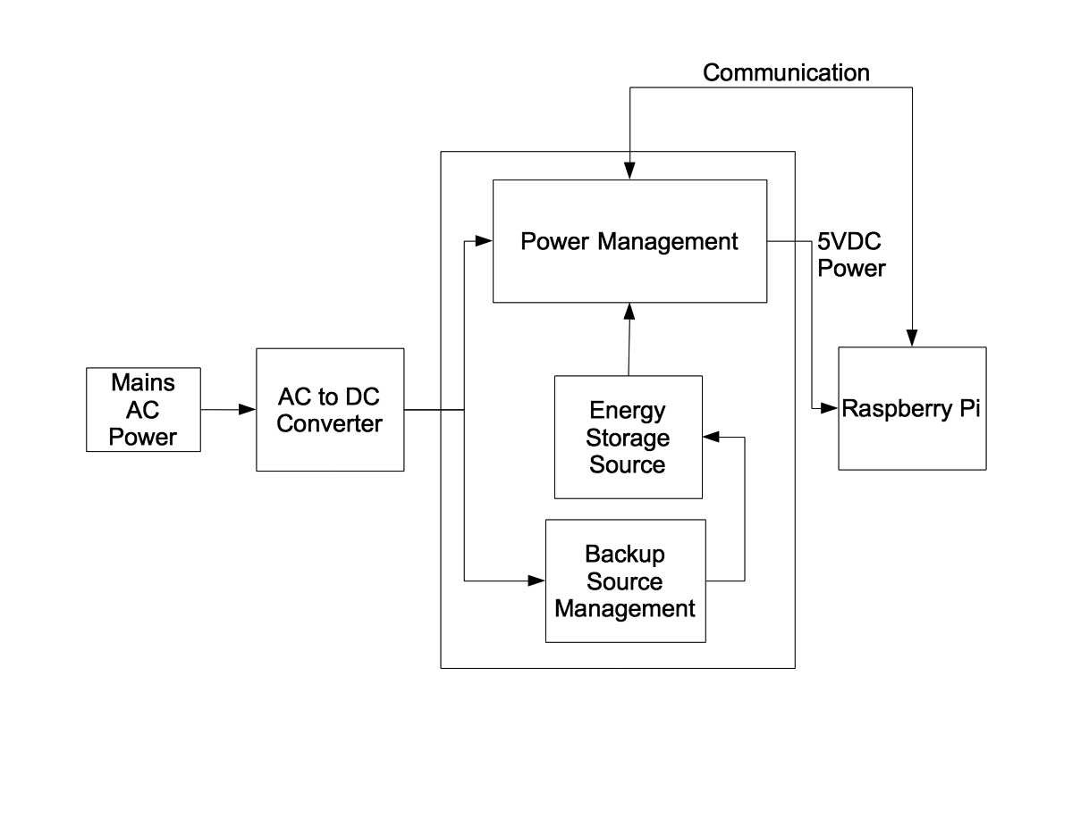
The AC-DC converter can output almost any voltage, but it is usually a voltage larger than the required input voltage of the load (the Raspberry Pi). Many UPS systems use 12VDC or 24VDC and then use a step down, or buck converter, (or heaven forbid…linear regulator) to produce the required 5VDC output to the RPi. If the AC power fails, the Power Management block automatically switches over to the the stored energy source to keep providing power to the load. There are lots of variations on this theme, but the usual method is to have a switch mode converter that provides a constant 5VDC output and switch its input between the AC-DC converter output and the Energy Storage by using a simple diode selector. So what you have during normal operation is a cascade of switch mode converters, each with its attendant power loss and noise generation due to the switching action.
This UPS is a bit different than most others. Here’s the block diagram:
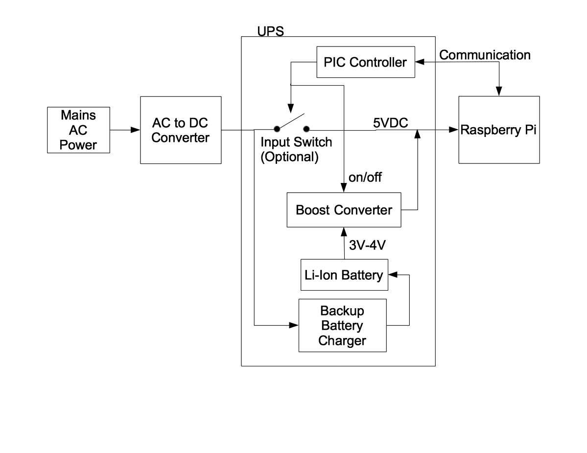
The AC-DC converter (the wall wart) outputs slightly more than 5VDC, say 5.15-5.25V, which is at the top end of the acceptable voltage range of the RPi. It is connected to the UPS output at all times — even when there is no AC power. The Energy Storage source is a single-cell Li-Ion battery with a typical voltage range of 3V to 4.2V and requires a boost converter to convert the battery voltage to the 5VDC required at the output. The boost converter is also connected to the output at all times but has its target output voltage set slightly below the wall wart output voltage. There is no diode selector because the boost converter manages the power switchover event at the UPS output. When the wall wart is providing power the UPS output voltage is held above the boost converter target voltage so the boost converter is inhibited from switching. When the AC power fails the wall wart simply changes state and becomes a relatively high impedance (something between 1megΩ and 500Ω, which is not much of a load). As the UPS output voltage falls below the boost converter target voltage it begins to switch and takes over providing power to the output. This switchover event needs to happen quickly in order to prevent any glitch from disrupting power to the load.
There are several advantages to this approach. It is inherently low power and low noise when operating on AC power (ignoring the required wall wart losses). The only power loss is some small overhead in the associated management system — about 500µA, or 2.5mW. The booster doesn’t make any noise if it’s not switching. It is low complexity, but the boost converter requires a bit of care to prevent any significant glitches at the output.
Index of Logs:
I have had a complaint that it is difficult to find information in the log files. Therefore I'm including a log index with a brief explanation of contents. (Sorry, but I can't get the Hackaday software to allow a link to a log file.)
- "Replacing the INACT pin with something that should work" is a description of what did not work with the first design attempt using the TPS61236p boost converter IC. It also describes the changes between the 18650 version and the 14500 version (the addition of the input switch and the decrease in charger current.
- "TPS61236p Design Considerations" is an analysis of the booster stability and response time characteristics.
- "UPS-14500-IS Early Results" covers the process of getting first prototypes to function. It also contains some performance data on the 14500 version.
- "Working UPS-14500-IS Prototypes!" is a continuation of the 14500 version debug process, design changes to correct problems, and scope traces showing output transition waveforms during the switchover event.
- "UPS-18650-NS Boards" describes changes made to the 18650 version after knowledge gained by evaluating 14500 version.
- "The 14500 "Hat-like" Concept" makes the case for the HAT version. It describes the design thought process and layout tradeoffs involved.
- "UPS-18650-NS Working Prototype" evaluation results of the 18650 prototype.
- "UPS-18650-NS Installed on the seismometer" shows the installation of the UPS on my seismometer and a python code example of its use.
- "UPS disturbance of seismometer" confirmation that the UPS works with the seismometer.
- "Going forward with the Hat version" contains a justification to proceed with the HAT version. Several different batteries were used to determine if a 14500 battery could hold up a 2.5A load long enough to shutdown the Raspberry Pi. It did...so we ordered PCBs to move the design along.
- "The Hat Version is Working" A short note on the performance of the HAT version.
- "More Booster design considerations - input/output capacitors" treats the problems of voltage and temperature variation of large value ceramic capacitors in a switching converter design.
- "Testing the 14500 HAT-like UPS supply with high current demands" is a description of Paul Versteeg's test methods and results of performing high current load tests.
- "Final Python Code...we're finished." Some code examples to use with the UPS. This is the last log we intend to file.
Here is where we've been and where we are today:
- We began by thinking that a LTC1872 boost converter would do the job. The advantages of the 1872 were a simple package (SOT23-6) and that it used external FET switches which we could select to match the intended load current. But the 1872 was a non-synchronous boost converter, requiring an external Schottky diode, which dissipated a lot of heat. In addition, the PCB layout of the external components was very sensitive and there was a lot of ringing in the switching loop that caused problems which were difficult to solve with a 2-layer PCB.
- So we scrapped the LTC1872 version and searched for a better solution, preferably a synchronous boost converter with internal switches rated for the 2.5A load with a 3V input. We implemented the second version using an 18650 Li-Ion battery and a TPS61236p boost converter. The booster performance was excellent, but the battery would not charge because of a misunderstanding of the INACT pin function of the TPS61236p.
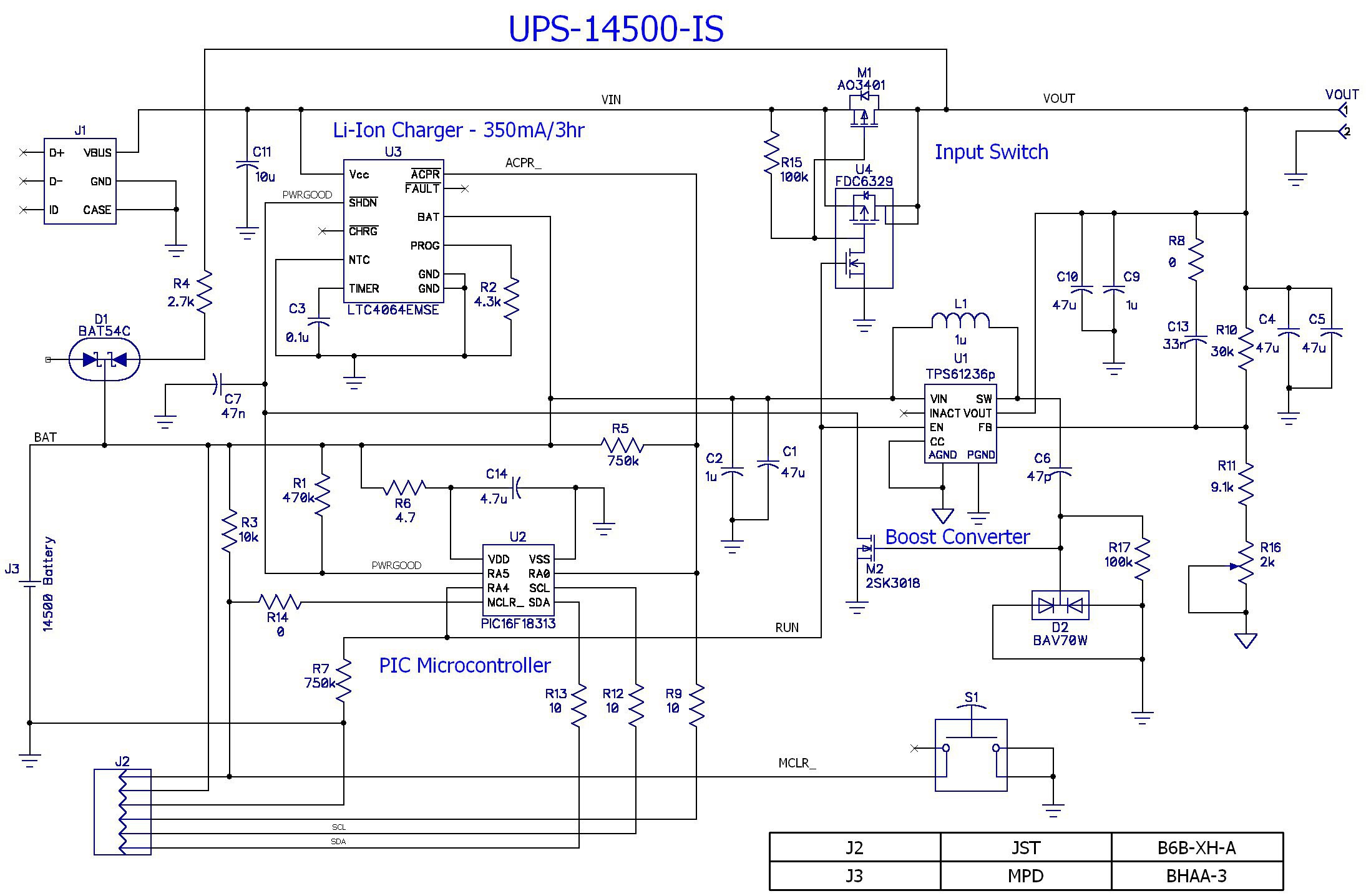
- Instead of changing the 18650 version I decided to implement the 14500 battery version, since it had more constraints than the larger battery version. This last revision is working correctly and the UPS is doing everything as expected. Here's the current schematic of the UPS-14500-IS (see the files section for this project to get the latest version of all of the schematics):
- The 18650 battery UPS is now working well (see logs).
- The Hat-like version PCBs have been populated and it functions as designed.
- The project is complete.
The Battery:
I wanted to have a UPS that was able to provide power for several hours. I have a seismometer that runs 24/7 recording data. It doesn’t require the wifi system or AC mains to do its job. PaulV, on the other hand, only needed to keep the power available for a relatively short duration and then power off the RPi gracefully. His application was useless if the AC mains failed. The battery requirements are vastly different. I selected an 18650 form factor lithium battery for two reasons: it can supply 2000+ mAh, it’s a standard form factor and it is easy to get from a variety of suppliers. PaulV needed a much smaller form factor, for space considerations, and only needed it to supply power for several minutes to ride out a short power outage, or a minute or so to safely shutdown the Raspberry Pi, so his battery is much smaller, a LiPo 600mAH.
The Battery Charger:
The big advantage of a single cell battery over multi-cells is that cell equalization is not required. There are also big tradeoffs in what features are contained in the battery charger: charger termination mode, recharge threshold, safety timer, cost, etc. Check out this link to get a feel for the impact that the termination voltage has on battery life. I concluded that a charge termination voltage around 4.0V, instead of 4.2V, would be optimal for a system that just uses the battery power when the mains power fails — about 0.1% of the time. Dropping the charge termination target to 4.0V increases the li-ion battery life by a factor of 4X — from 500 charge/discharge cycles to 2000 charge/discharge cycles. What you give up is about 25% of battery capacity during a power failure event. That was OK by me. My overall philosophy is to minimize the amount of maintenance while maximizing the longevity of a system, so this tradeoff was easy to make.
Unfortunately, there is only one battery charger that I could find that offered a 4.0V termination voltage — the LTC4064 ($3.65 from Digikey in Qty=1). So be it. If you can compromise on cost/hassle, then selecting a charger with a 4.1V termination will yield a 2x improvement in battery life. There are a lot more of them from which to choose. Or…you can roll your own, which I don’t recommend. There is a history of bad decisions made when designing lithium battery charging systems (think Apple, Sony, Boeing, Samsung, etc.). It is better to let the big boys (LTC/ADI, TI, Maxim, etc.) determine what is required in a lithium battery charger. They have a lot of experience to offer for $3.65. It was not important to either PaulV or me that the battery be recharged quickly, a 6-hour recharge cycle is not an issue. Since the mains fail so infrequently a quick recharge cycle is not important. Fast recharge is the domain of the portable, robotic or wearable applications which did not interest us.
You must allocate the battery charger current as a part of the wall wart capacity. A 0.5A charge current is an appropriate upper limit for a 2-2.5A wall wart. This leaves 1.5-2A for the RPi and its peripherals.
The boost converter:
It turns out that the key to the boost converter is to use an IC that is synchronous, with internal switches. The component count goes way down along with other advantages. The output switch can be eliminated because those switches are now contained in the boost converter. And the booster can prevent high currents flowing during short circuit events. The biggest problem was finding a boost converter IC that had internal switches that could handle 6+ amps. We eventually stumbled on the TPS61236p. The data sheet even includes a graphic showing best layout practice and extensive layout tips (are you listening LTC?)
Another problem is heat. If the boost converter is going to run for a long while, it is going to generate some heat since it is not 100% efficient. There are a few solutions for this: make the PCB large enough to dissipate the heat, use heat sinks, or blow air over it. The PCB needs to be about 2500mm^2 (4 square inches) in order to keep the temperature rise to a reasonable number when the boost converter is running at full load. Of course if you are only running the boost converter for a few seconds, or the load is smaller, then heat may not be an issue.
Removing the input switch:
PaulV convinced me that we could eliminate the input switch. Its purpose was to disconnect power to the RPi in order to force it to boot properly. PaulV uses the RPi’s hardware watchdog to reboot the RPi after 10 seconds of inactivity so the “stuck at power off” problem goes away (see this link). Removing the input switch also eliminates the associated voltage drop and power losses.
Unfortunately, recent Raspian Jessie kernel updates changed the systemd watchdog operation so that it no longer will reboot the Pi after issuing a “sudo poweroff” or “sudo shutdown -h now” command . So the input switch was added back to versions of the UPS with shorter battery capacity and needed to reboot the Pi after a power failure. The input switch is not required for larger battery capacities since it is expected to ride through most power failure events without shutting down the Pi, and if it has to shutdown the Pi the probability that the power returns during that brief event is very low.
The Control and Interface:
In the interest of reduced part count and system flexibility I decided to use a PIC microcontroller to control the functionality and implement the interface to the RPi. I had to learn about PICs and how to program them . I went through 4 different PICs before finding the right combination of functionality and cost in the PIC16F18313/23. Along the way the PIC pin count dropped from 14 to 8 as the circuitry got simpler.
There are a lot of ways to interface to the RPi. The interface needs to communicate the status of the power and the battery voltage to the RPi, and the RPi has to signal the UPS to shutdown. You can do all this with only two GPIO pins, but the battery status is just high or low, which doesn’t give the RPi a lot of options. I decided that the best interface was I2C. I implemented the standard smbus read_word protocol to send a command to the UPS while also getting its status and battery voltage returned in one message. There are only two commands: continue or shutdown. There are three self explanatory status bits: PWRGOOD, BATLOW and SHUTDN. The battery voltage is returned as the second byte in the form of a ratio of
where Vref = 2.048V. The PIC can do this without using any external pins if its supply is VBAT.
The package:
It’s a lot simpler, fewer components, and more efficient than where we started from. The PCB fits underneath the 18650 or 14500 battery holder to save space — I think this is a pretty elegant solution in terms of space. It also makes for a larger PCB to dissipate the heat generated by the boost converter.