Top breadboard is the VCO with the CEM chip on the left. Bottom breadboard is the power supply.
The small one on the left is a simple CV pot. I used it to test the pulse width.
I know it is such a mess..
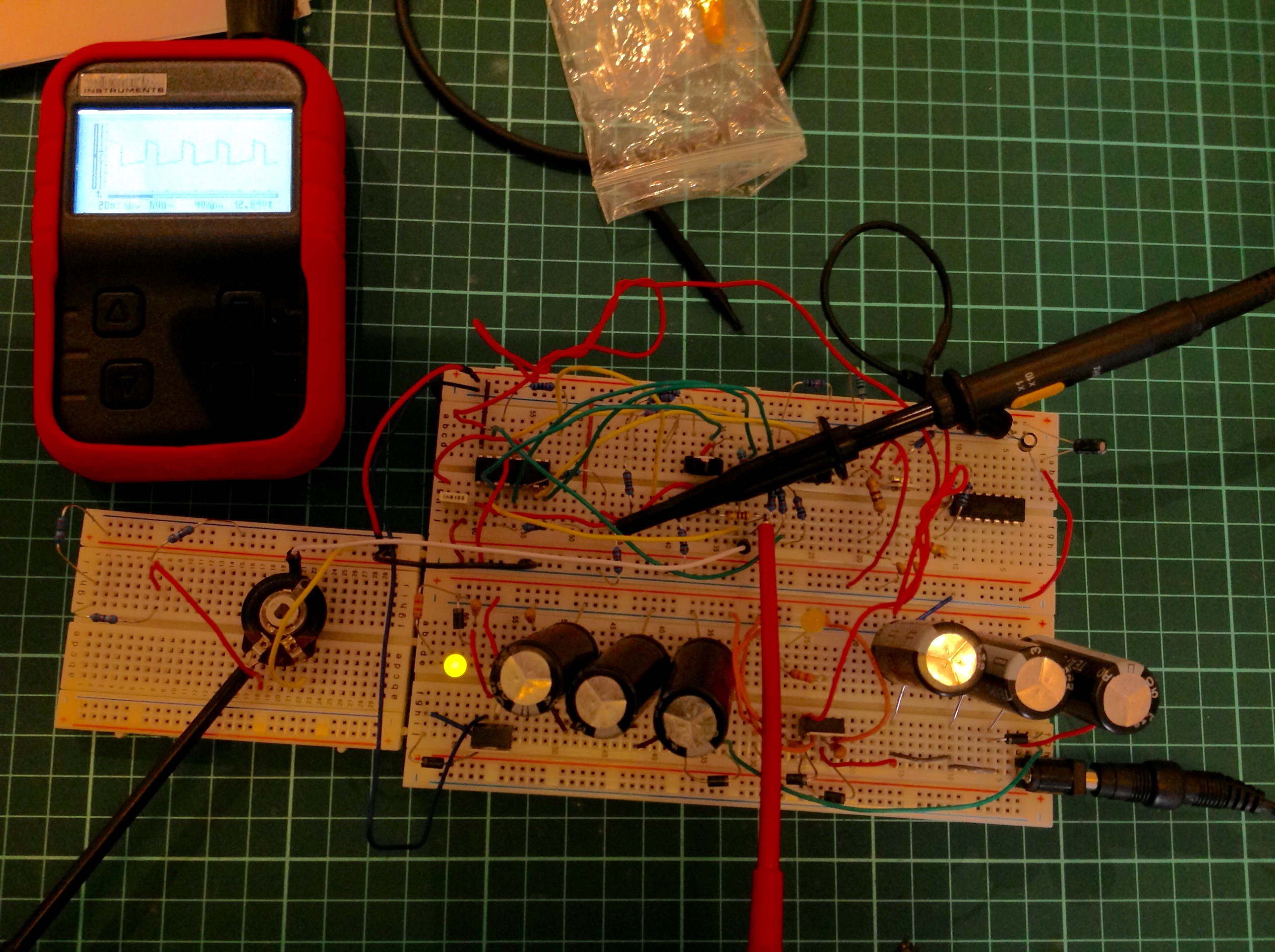
The design is mostly inspired by the Memorymoog, but I'd like to include VCOs sync, which is lacking in it.
Next step is calibrating the 3 variable resistors to tune it at 1v/oct. it won't be an easy task...
Discussions
Become a Hackaday.io Member
Create an account to leave a comment. Already have an account? Log In.