 polyfractal
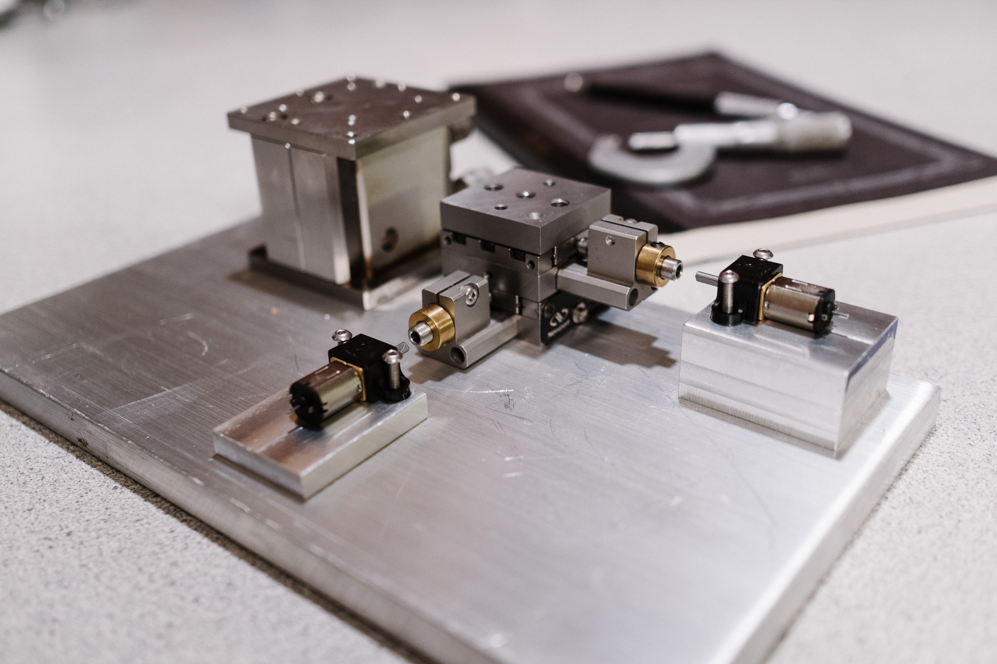
Back to work! After a long hiatus, I'm making progress on this project again. The next step is to start building the mounting hardware for the X/Y stage, motors, vertical adjustment and optical engine itself.
Let's look at this setup individually. First up is the X/Y stage:
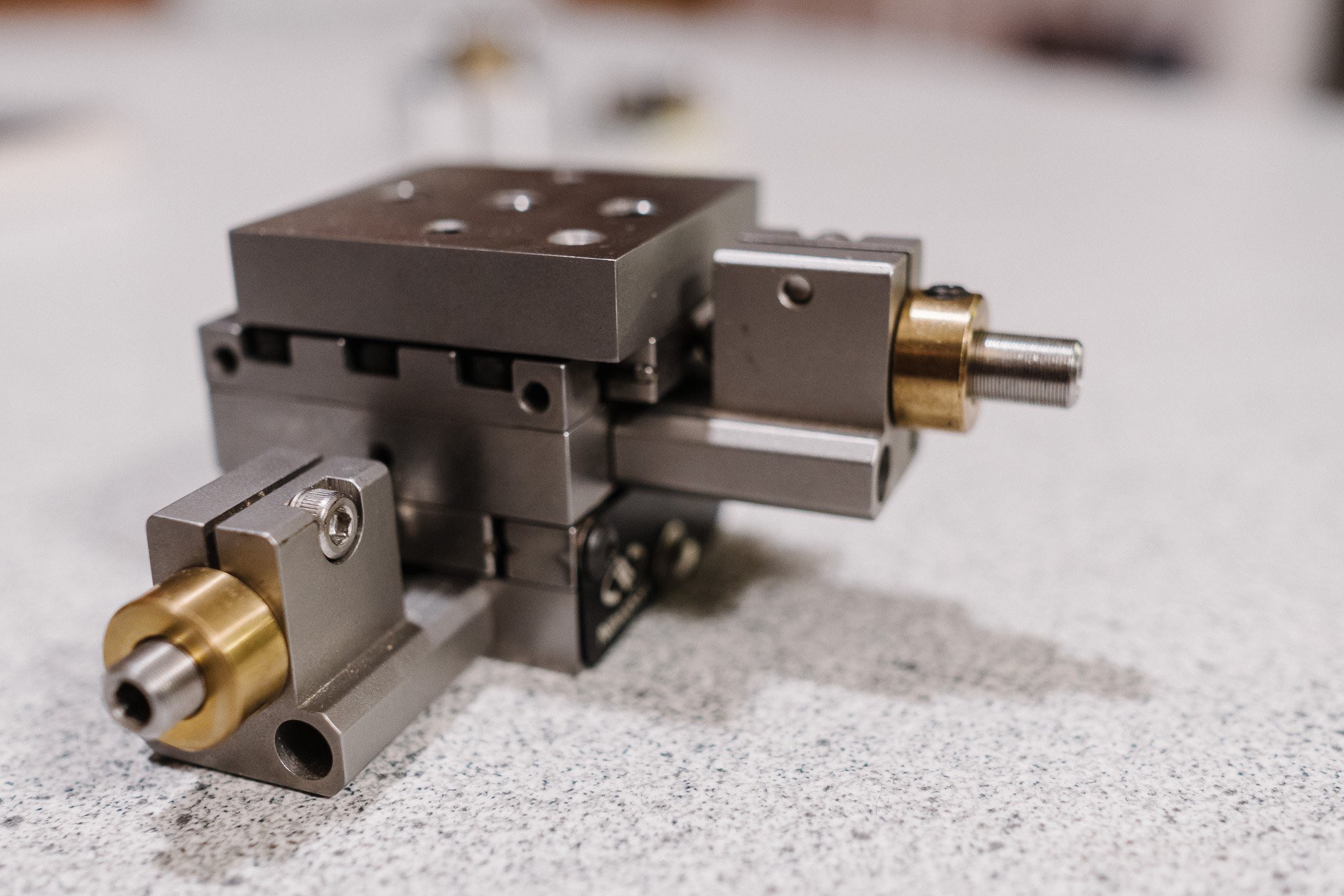
This is a Newport ULTRAlign M-461-XY-M stage, capable of traveling 12.5mm in both X and Y directions. It's stainless, and sports a bunch of fancy features like crossed roller bearings. These are often used in optics labs for precisely aligning various components. I picked it up reasonably cheap on eBay some time last year.
These are typically adjusted with manual micrometer heads, but I replaced them with 80 TPI hex micrometers, so that they could be driven with motors directly. The 80 TPI equates to 318 microns per revolution of the micrometer.
Next are the gearmotors and their mounting blocks:
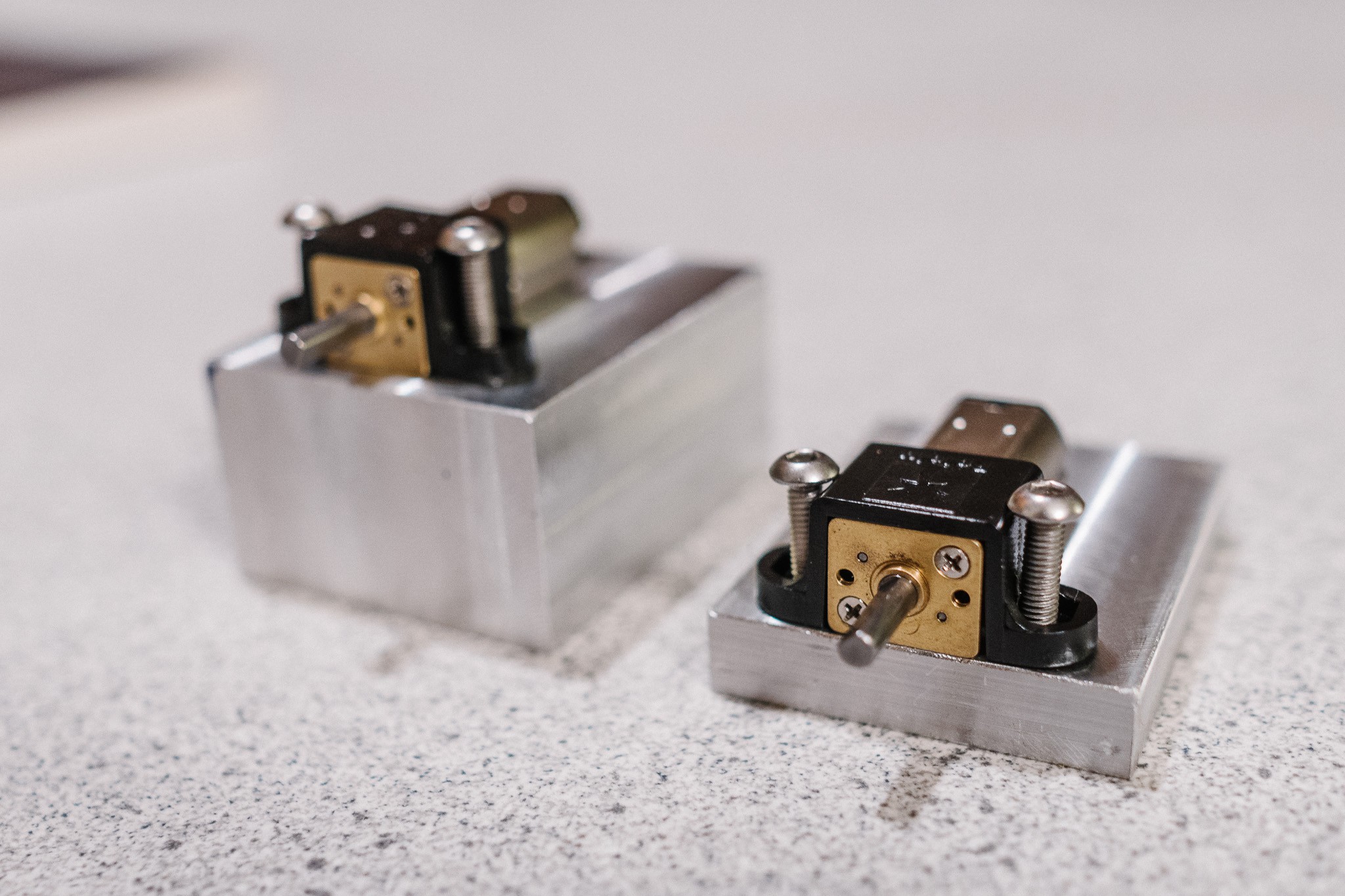
The motors are small 1000:1 brushed gearmotors. They have an extended shaft in the back that can be used to mount a quadrature encoder for position tracking. I chose these high reduction motors because I don't need speed, and the high gearing allows for many encoder pulses per rotation.
The encoders I purchased are optical encoders that pulse 20 times per rotation. With a 1000:1 gearmotor, that's 20,000 pulses for one rotation of the output shaft. Coupled with the 80 TPI micrometers, the theoretical resolution is one pulse per 15.9nm (lol).
Obviously, I don't expect to get anywhere near this resolution in practice. Stiction alone will be significant at these low speeds and high TPIs. And the backlash in the gearmotor gear train is noticeable enough that you can feel it by hand.
Lastly, the optical encoders emit sine waves instead of square waves:
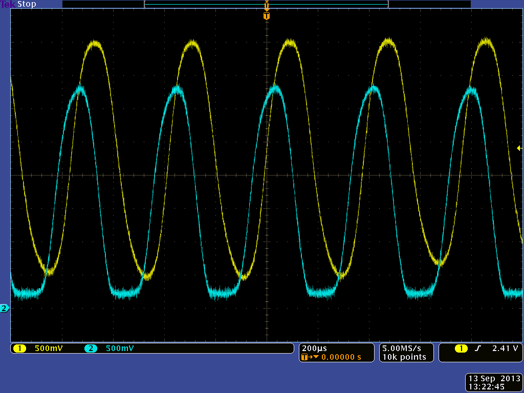
Which will cause a certain amount of inaccuracy due to signal processing, not to mention the noise on the signal itself.
All that said though, I think getting reasonable micron/tens of micron resolution is achievable.
The motors are mounted to custom fabricated aluminum blocks. I recently picked up a horizontal/vertical milling machine on craigslist that I've been cleaning up. I'll be using the mill a lot more in the future to fabricate high accuracy parts needed for the setup, something my 3D printer really just can't do.
Lastly, the vertical stage:
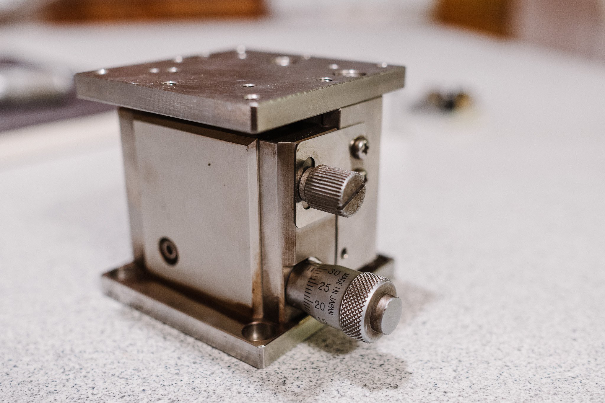
Another eBay find, this essentially a vertical version of an X/Y stage. Turning the micrometer moves the head upwards, and will allow me to dial in focus easily. I don't plan to motorize this (yet)... manual focusing will be fine for now.
All the components will eventually be mounted directly to an aluminum plate for permanent alignment:

Discussions
Become a Hackaday.io Member
Create an account to leave a comment. Already have an account? Log In.
You might find this interesting: #Hacking any linear slide/bearing into piezo motor
I have no connection with that project other than remembering it.
Are you sure? yes | no