 David Brown
So, time for some more updates;
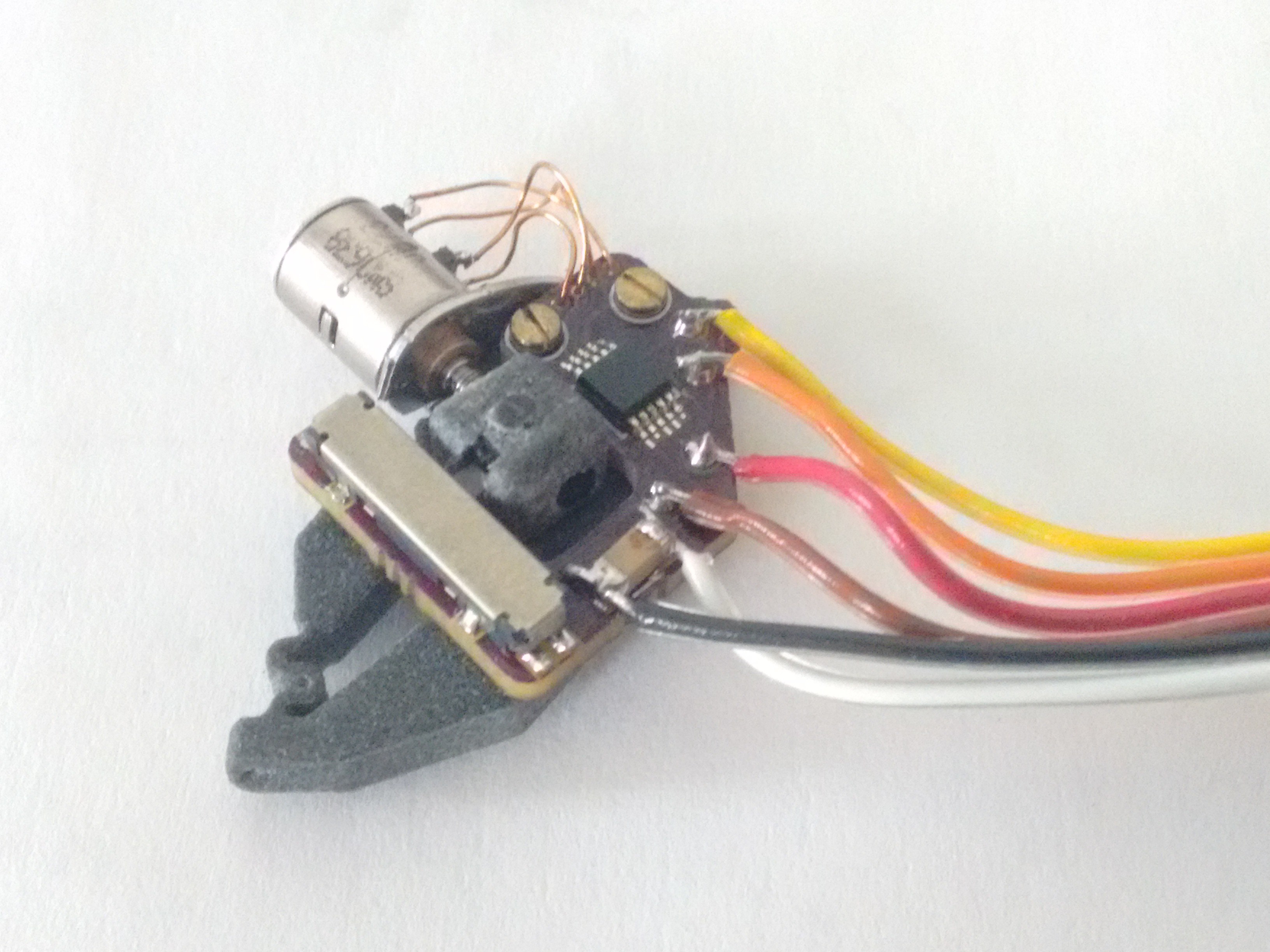
I recieved the most recent printed parts from shapeways and re-built the test actuator.
The housing for the lead-screw nut had some dimensional issues as did one set of the actuator bodies. It appears that due to the dimensions of the parts when the print starts or finishes ( I can't tell which) there is significant shrinkage in the initial layer or after cooling that leads to warp/dishing of one of the faces as can be seen;
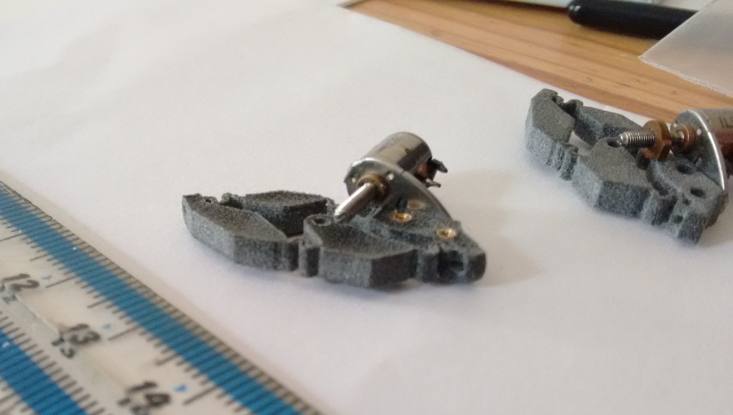
The right most part has a good level surface but the one that was opposite it has a concave surface. [It appears from limited evidence that the 'black' material does not suffer from this defect and that it is only the 'grey' that does so]
Using the ok parts the test actuator went together after application of needle files and sandpaper, but the combination of the friction betwwen the shaft thread and nut (which is not insignificant to begin with), the nut housing and the actuator body or PCB, meant that the motor had barely enough torque to move more than a fraction of a millimeter.
The main issue is that because the core of the motor is only 3mm diameter it is not able to generate sufficient torque for this application. I am sure that with a slightly larger diameter motor and several itterations to compensate for the behaviour of the 3D printer, that this arrangment would be a viable mechanism. The geometry and KiCad PCB files for this version are available in the downloads section for anyone interested.
So time to re-evaluate and change up the design to itteration A2. If say 10mm diameter threaded shaft motors were available then I would do a re-design to suit. Unfortunatly there is a gap in available threaded shaft motors (readily available surplus I should add) between the ~6mm camera lens motors and ~NEMA 23. Another reason to re-think is the wiring required for control and feed back needs to be very flexible and thus far I've been unable to find a reasonably priced candidate.
In order to maintain the required small actuator end my new plan is to move the drive mechanism to be above the 'base frame' as the terminlology for gough-stewart platforms goes. By using an arrangmeent where the actuator is replaced by a 0.5mm wire rope and compressions spring so that the legs of the platform are formed by the wire tendons under tension from the springs.
The end of each tendon will then be pulled by a lever arrangment that divides the displacement at the stepper end by a factor and so allows the small displacements of the platform to be achieved. I'm looking at using PTFE tubing to reduce the friction and capstain loads in the system, with NEMA 8 motors to provide power and also give 1.8deg step resolution. I need to put together the calculations for the lever ratios required and evaluate the tension in the legs to overcome friction/stiction to allow smooth operation.
Discussions
Become a Hackaday.io Member
Create an account to leave a comment. Already have an account? Log In.