 Timo Birnschein
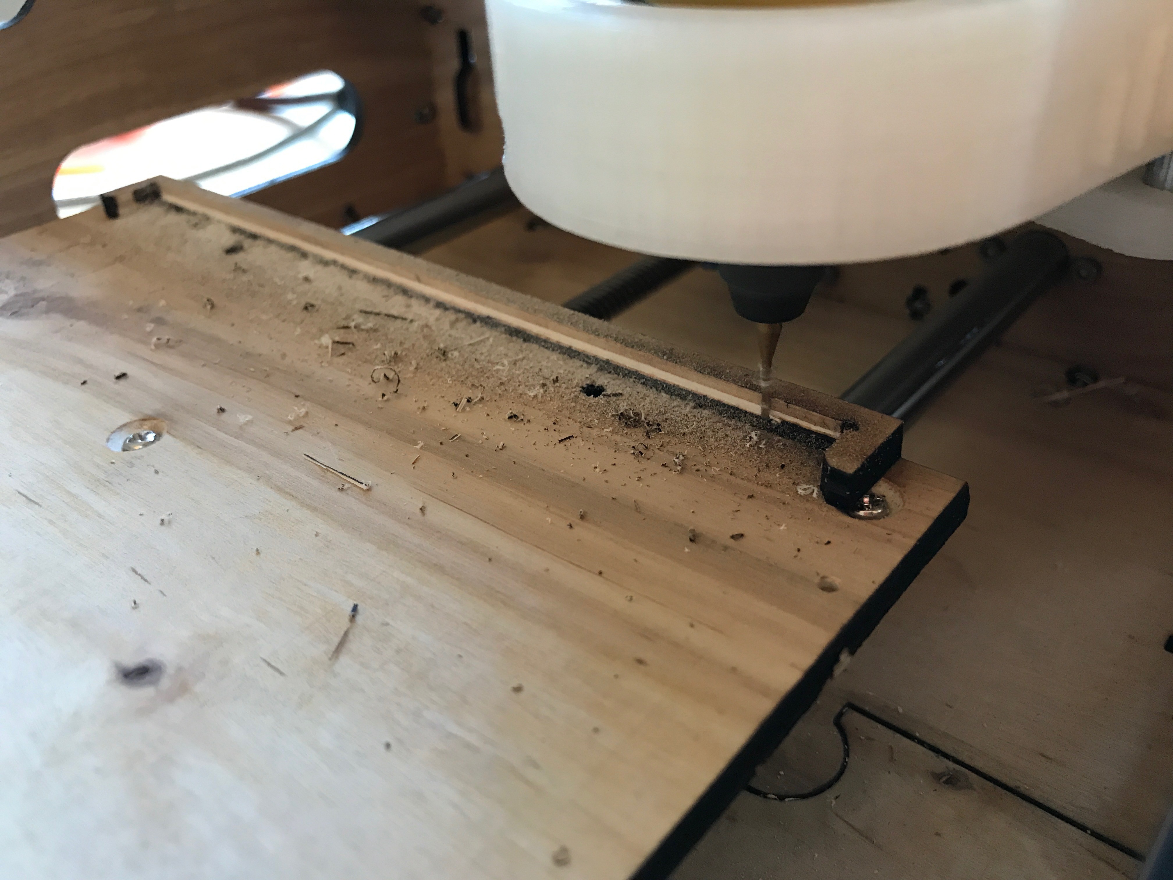
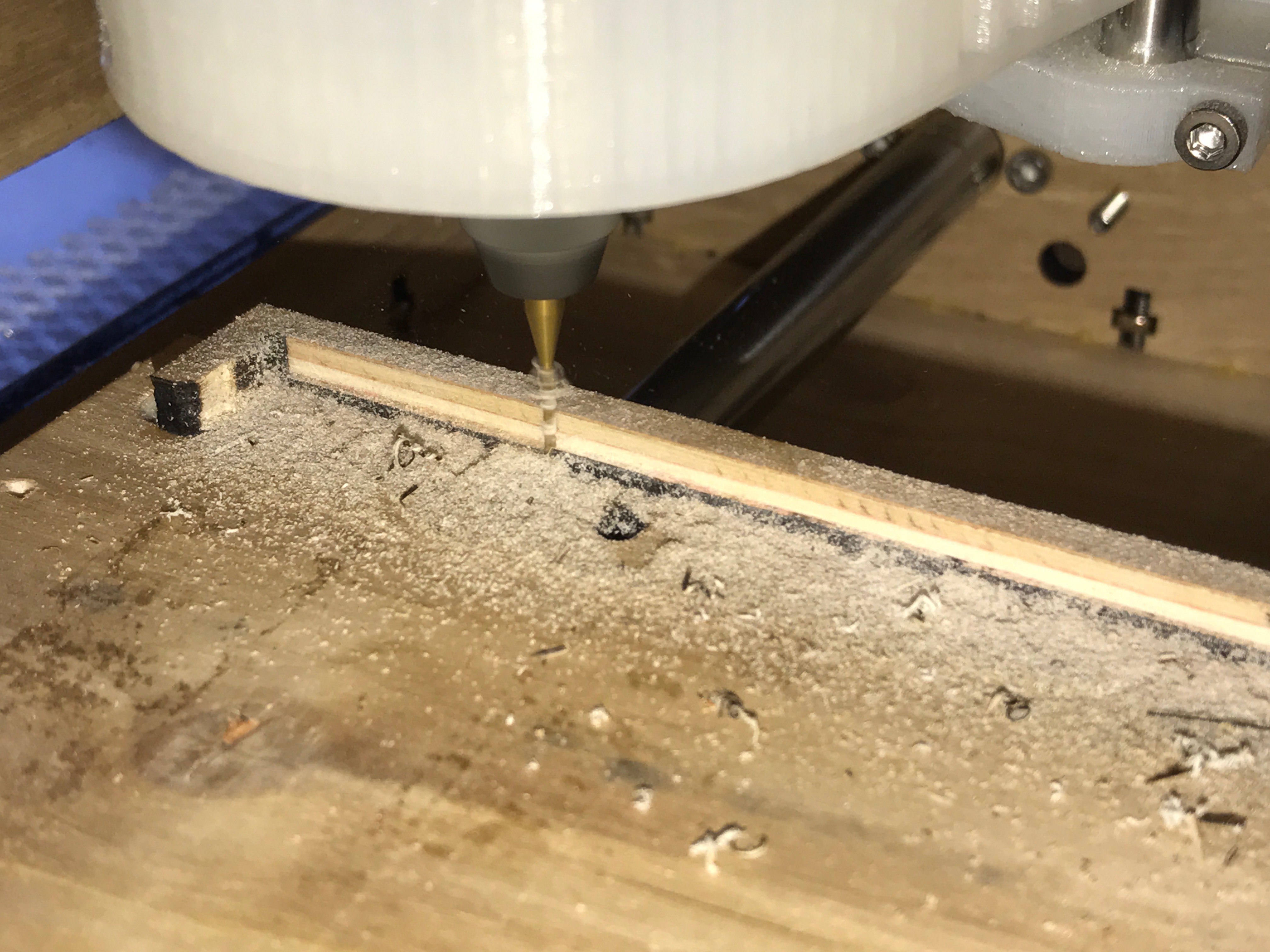
A couple of days ago, I managed to install the wooden mill bed. I made it from the most flat sheet of plywood I could find so that I don't really have to deal with any Z-height calibration on the copper board itself. Just put it in there and start milling. I also glued the X-Limit Fence (?) in place and milled it down to be absolutely parallel to the Y-Axis. To do that I created a super simple gCode file by hand and let it run. It turned out really well and I'm now ready to do the Y-axis offset calibration to mill the bottom side of PCBs.
Milling top side of PCB
- Home X,Y
- Glue Copper Clad Board to upper left corner of table using double sided tape
- Move to 0,0,5
- Attach Z-Probe to mill bit and PCB
- Home Z
- Load file into PCB-Gcode-Controller
- Optimize file
- Mill top side in positive space
Milling top side of PCB
- Home X,Y
- Glue Copper Clad Board to upper right corner of table using double tape
- Move to offset
- Use G92 Command to set new machine location (like G92 Y-162) [requires one time calibration of Y-Offset to be able to mill properly in negative space]
- Attach Z-probe to mill bit and PCB
- Home Z
- Load file into PCB-Gcode-Controller
- Optimize file
- Mill bottom side in negative space
That's literally all that's required for etching. The same is true for drilling and outline milling.
Steps to etch double sided PCBs:
- Mill top side
- Mill bottom side
- Drill bottom holes
- Mill outline
One remark: I haven't found the settings for Z-depth per run in the PCB-Gcode UPL script for Eagle. That means it tries to mill the outlines of the board in one go! This will likely break your mill bit because it imposes very high stress on it! I currently modify the gcode by hand by copying and pasting the milling multiple times while adjusting the Z-height every full run around the outline of the pcb. Not ideal, but if you want full automation, I suggest using a different software or modify the ULP script.
Discussions
Become a Hackaday.io Member
Create an account to leave a comment. Already have an account? Log In.