 Timo Birnschein
Milling a PCB:
You have come this far, that is both admirable and awesome and I thank you for following along!
But that also means you need to get the settings and instructions now to be able to mill your first PCB successfully. In other words, this log entry might become a little wordy but I will try to keep it as short as possible since I'm not a fan of reading 20 pages to get the bottom of a simple step myself.
- Fire up eagle and load your board design
- Move your entire board slightly away from 0,0 which should be at the bottom left. This is important because otherwise the mill will eventually end up running into negative space on the TOP layer and that is definitely NOT what you want. We want to keep things simple. Move it away by 5 mm in X and Y.
- Use the info tool and move your outlines from the layer 48 Document to the layer 46 Milling. This will enable the pcb-gcode script to find your outline and generate your milling path for the outer contour of the PCB. Please keep in mind that the end mill will run exactly in the center of the mill line. There is no outer offset based on the diameter of the endmill being calculated by pcb-gcode! You have to design that into your board layout yourself!
- At the top of eagle you find your command text field. Type "run pcb-gcode-setup" and hit enter.
- Change all fields to the following settings if the settings I have provided in the pcb-gcode patch archive didn't do that for you already:
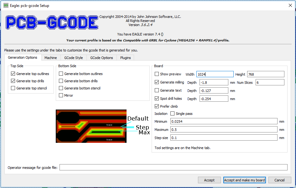
The new item that I added so that your outlines can be milled without destrying your endmill is on the right. Num Slices is the number of layers for cutting the outline. So at -1.8 mm cutting depth this results in {-0.3 mm, -0.6 mm, -0.9 mm, -1.2 mm, -1.5 mm, -1.8 mm} different cut depths.
Since the board in my example didn't need a bottom side, I deactivated the bottom layer features. However, I think the following should be selected for a dual layer board:
- Generate top outlines (there is a bug in this menu: If the top outlines are not selected, the top.etch file will not be generated. I might hunt that bug down later...). We will ignore the top.mill file!
- Generate top drills (we want to drill first)
- Generate bottom outlines (this is your mill file for cutting the outline of the board. We need to do that LAST!).
- The bottom.etch file will be generated automatically.
Please note: I have deactivated Show Preview because it annoyed me after a while. When you know what the result should be, you can deactivate it. It speeds up the process significantly - not that it's very slow in the first place...
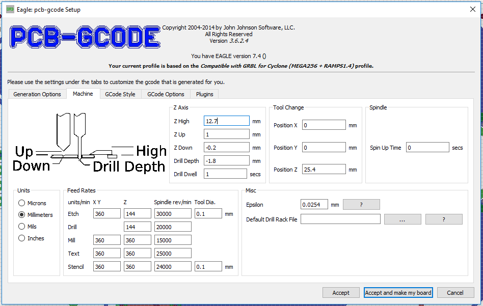
The machine uses the speeds that OtherMill suggests for milling FR1 copper clad board. That is by no means super fast but it looks impressive enough. My endmill holds up to that speed and I'm fairly confident that my 10 mill bits will last quite a long time for their huge $9 investment (for all ten).
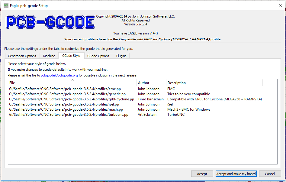
Select the grbl-cyclone.pp file and go to the next tab.
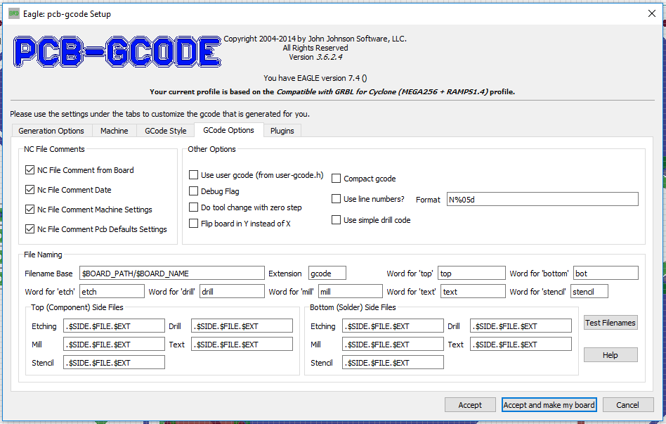
- That's it! Hit Accept and make my board.
Now, you should have a range of files in your project folder.
- filename.top.etch.gcode
- filename.top.drill.gcode
- filename.top.mill.gcode (ignore forever)
- filename.bot.etch.gcode
- filename.bot.drill.gcode (ignore forever)
- filename.bot.mill.gcode
We do not want to drill twice. If there is a tiny misalignment in your PCB machine, you will not drill into a hole but slightly off the center of that hole. It is very likely, that your drill bit will snap and we don't want that! Specifically, if it ends up in your eye!
Preparation of the PCB:
Make sure the PCB is flat. If not, use some gentle force to flatten it. When it is flat enough, use double sided tape and apply it with even distance throughout the area you expect the machine to mill. More doesn't hurt but it would be good to be able to remove the PCB from the mill bed after milling without destroying neither the PCB nor the bed.
Apply the PCB to the top left corner of the mill bed for the top side and make sure you have it aligned properly and totally parallel and flat to the top mill bed alignment fence. This step is important!
Fire up grblController with my modifications and connect to the mill. Go to the PCB Milling tab and home the machine. Otherwise it won't do anything but lock you out.
========================================================================
After homing, make a dry run in thin air without Z-probing and without any endmill attached. Make sure the system works properly before you even attempt to mill a board! Make sure your Proxxon actually spins up when milling should start.
========================================================================
Then, attach your V-shaped endmill and connect the probing wires to the PCB and the endmill. I press the one wire with a crocodile clamp onto the copper clad board and I attach the other wire with a crocodile clamp to the end mill. MAKE SURE YOU HAVE PROPER CONNECTIONS or you will break your endmill. I suggest testing it first by just touching your endmill with the second wire from the PCB to check if the machine stops instantly during the probing run. Check your wiring if it doesn't do that! Remember, the pin must be pulled to ground because it uses the internal pullup of the micro controller and it looks for a low signal on the I/O.
Confirm that the wires are connected using the check box and hit the Probe Z0 button. Z-axis moves, gently touches the surfaces and stops. Be prepared to emergency shutdown the mill during the first couple of Z-probes... It's probably a good idea to use even slower feedrates.
All done, let's get to business:
- Load up your top.etch.gcode file.
- Remove all your probing wires.
- Hit Start!
Milling begins now, the spindle turns on and you should see the system running through the PCB. Wait until done.
Move the spindle to safety and remove the v-shaped endmill and replace it with the drillbit of your choice!
Load top.drill.gcode and repeat the Z-Probing step. Be careful to actually have a proper connection. The drill bit will just break instantly of you don't.
It is wise to run the Home X and Y command first by pressing the button because you attached a new tool and it is likely that something moved in the process.
After successful Z-probing, hit Start again and wait until finish!
Move the spindle to safety and remove the drill bit and replace it with the v-shaped endmill!
Remove the PCB, clean the print bed and free it from any remaining double sided tape. Since it is wood in my case, I scrape it off instead of using chemicals. If the bed is not properly flat, you will run into problems with etching now. Apply the double sided tape on the TOP side of the board you just etched successfully and glue the board to the TOP RIGHT edge of the mill bed such that the old top left corner of the copper clad board is now in the top right alignment corner of the bed facing down.
========================================================================
At this point, I'm going to assume you have calibrated your X-Offset already!
If not, a drilled hole on the top side must line up perfectly with a drilled hole on the bottom side. In my case the offset was 160.3 mm in X and it should not be vastly different on your system. Maybe by 0.5mm but not more. That should give you at least an acceptable test PCB for starters. If you're planning on using DIP and though hole parts. Test it and calibrate it using one or two holes only! Drill a hole manually at X=60, Y=5 and then move to the bottom coordinate system and drill X=-60 Y=5 and it should line up perfectly!
========================================================================
- Load the bot.etch.gcode file from your PCB project directory.
- HOME THE MACHINE!
- Hit the Set Bottom Side Coordinate System After Fresh Homing button (WARNING: This will move the end mill to the new X0 position in the other corner. Make sure the path between X0 on the left and the new X0 on the right is free of obstacles or your endmill will break! I will add a checkbox for this later to make it safer and more idiot proof)
- Attach probe wires
- Probe for Z0
- Hit Start!
- Wait until finished.
Repeat with bot.mill.gcode but please attach you mill bit to the Proxxon spindle.
- Attach probe wires
- Probe for Z0
- Hit Start!
- Wait until finished.
Please keep in mind that the end mill will run exactly in the center of the mill line. There is no outer offset being calculated by pcb-gcode! You have to design that into your board layout yourself!
After all this you should have a board done. So much text! If you do it twice, you won't need any of this anymore because it's actually just pressing three buttons and changing some end mills and it's done. Takes no time to do but the learning curve is rather steep.
Congratulations! You have successfully milled your first double sided board with drilling holes and milling the outlines!
Thanks for reading all of this and I hope it helps you to get started!
Discussions
Become a Hackaday.io Member
Create an account to leave a comment. Already have an account? Log In.
Witam.
Wykonałeś świetną robotę. Długo szukałem rozwiązania mojego problemu, dopóki nie znalazłem twojego przewodnika, który wyjaśnił mi wszystkie problemy. Gratulację. Wielkie dzięki. Pozdrawiam.
.Stanisław.
Are you sure? yes | no