Well, an absolute newbie in soldering might have a hard time with building this robot. For the power wires some AWG 26 can be used while all other connections should be done with a thinner wire as for example 0.2mm polyurethane enameled copper wire.
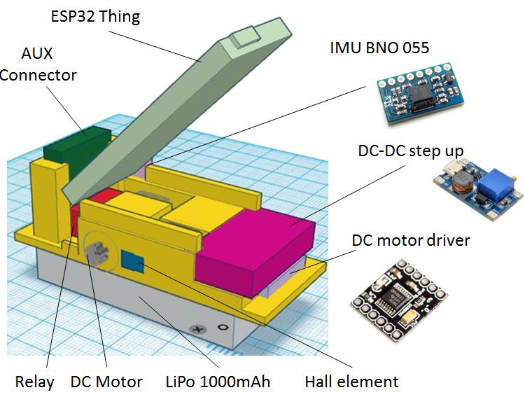
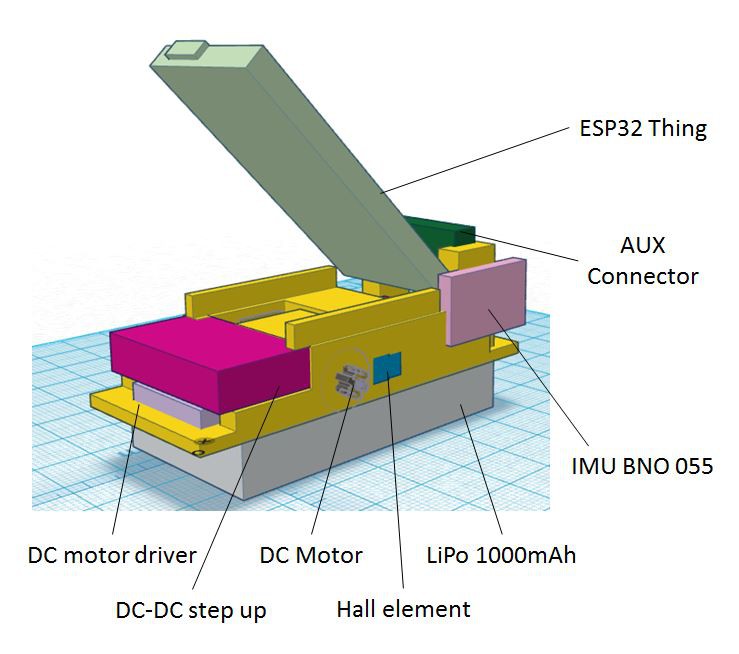
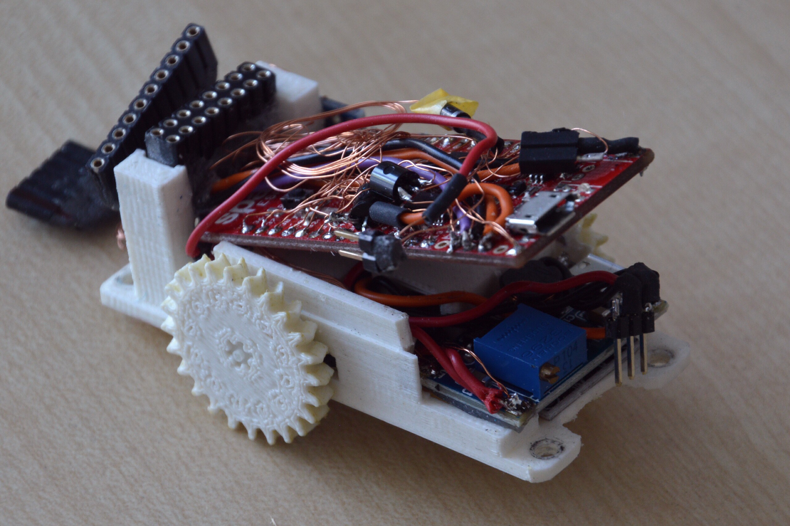
The controller holder 3D print sits on the LiPo and is made to hold all electrical modules as shown on the pictures. There are different breakout modules for the various electronic elements available. The picture shows the particular models the 3D is designed to. With these picture it should be easy to find an appropriate in the various internet shops. ESP32 Thing is the ESP32 development board from Sparkfun and had the best dimension (at that time).
![]()
![]()
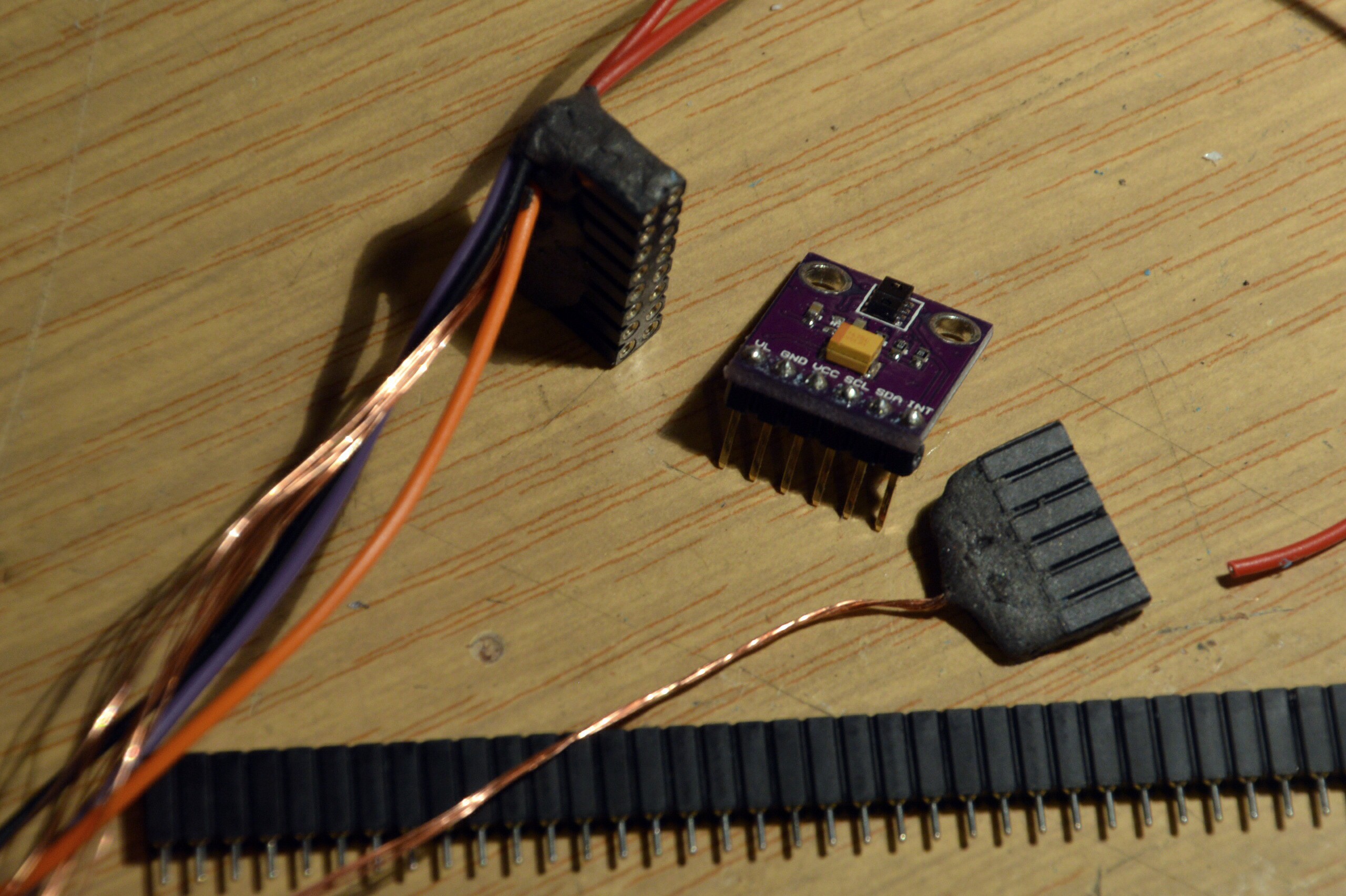
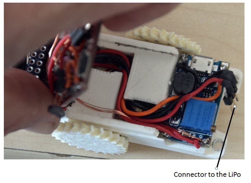
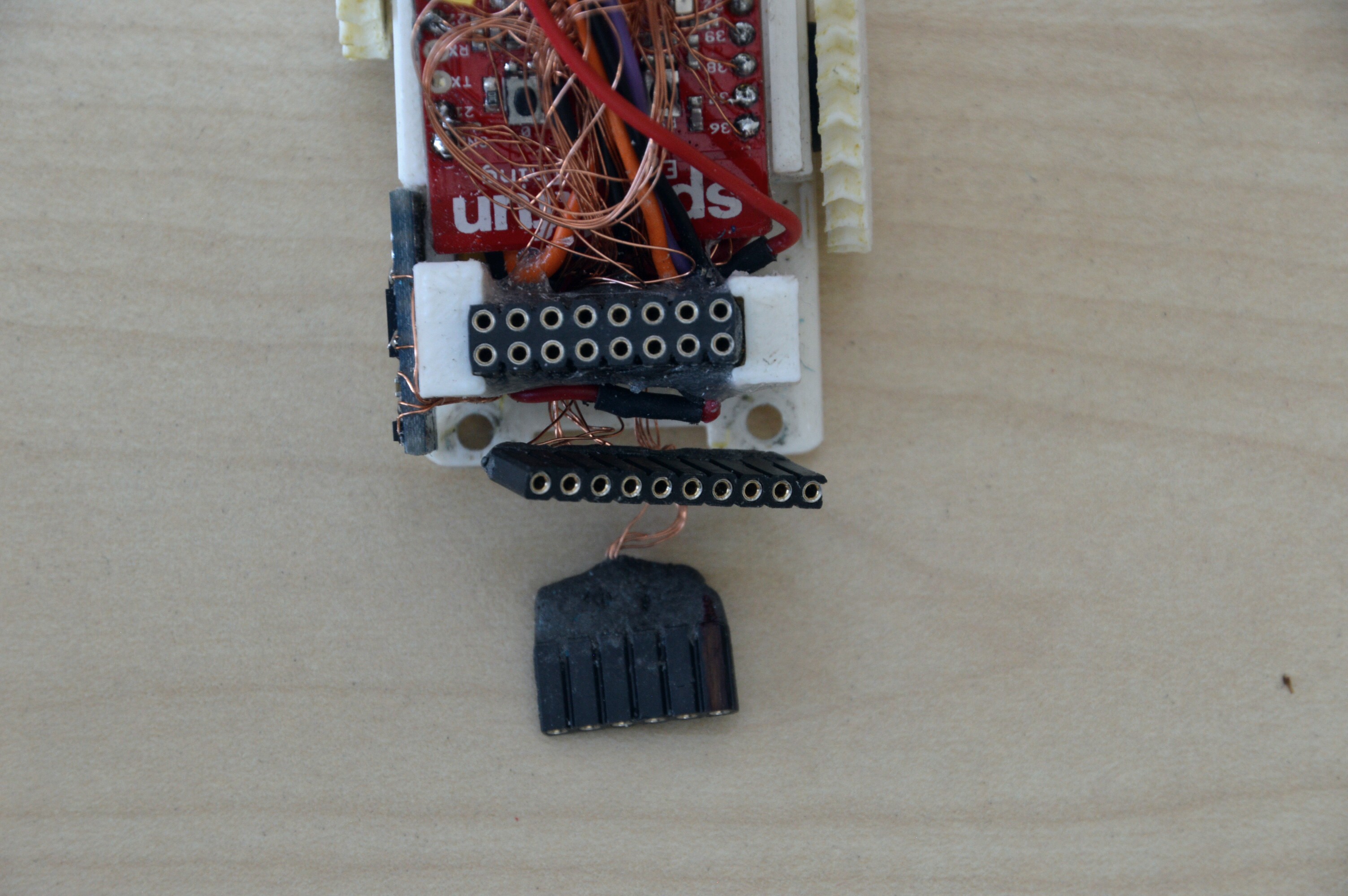
In order to ensure the capability to disassemble the robots some connectors are used. Most of the usual connectors are to big in size for this compact robot. Instead this connections can be made with pin headers. The LiPo connector has a pin header isolated with heat shrink tubes.
![]()
![]()
But as this consumes to much space for the other connectors their isolation can be done with epoxy putty. By the way, the LiPo connector here is made with 3 pins – Ground on both outer pins – in order to avoid a wrong polarity.
![]()
The wires from the DC-DC converter, the LiPo and motor driver can be routed between the motors to the back. As it’s nessecary to flip up the ESP32 board for accesing the screws, all wires needs to be feed under the AUX connector from the back side to the controller board.
![]()
The connectors for the front side proxy (I2C) and the connector for the bottom proxies needs to be movable while screwing the controller module into the robot. Therefore the wires need to be made long enough. When assembled the excess wires can be winded up and be placed on top of the ESP32 board.
Discussions
Become a Hackaday.io Member
Create an account to leave a comment. Already have an account? Log In.