 Pierre-Loup M.
Hello!
The boards have been received a few days ago. They are really nice, beautifully looking, and... almost ok.
It has been a long way before I could start to debug and fine tune the program running on them. Three hours to figure out how to burn the bootloader and the main program, using an Arduino as ISP. Three hours to find out that some tutorials on Internet advice to set a 10µF cap between ground and reset on the board used as ISP, and that you need to set this cap. At least, on the board I used it was needed.
Then another three hours to understand why the display was not working. At all. No light, no blink, not even a wink! Three hours to read the program again, looking for anything that could go wrong, looking at the schematics of the board, looking at the gerber files I sent to the PCB supplyer. And finding absolutely nothing that could be the problem. And enventually, following the traces on the PCB, one by one, finding out that the decoupling capacitor and the iset resistor of the MAX7219 chip had been swapped by the manufacturer... 2 minutes, a tweezer and a small blowtorch later, the PCB was OK.
So, the program has been tested, debugged, re-written in some cases, and everything is fine! I'm really glad that, some program details and the components swapped by the PCBA manufacturer put aside, it came right by the first time! The timer does its job, and does it well! Time's missing this days, but the next step is of course to mount this timer into a UV printing bed to test it in real conditions!
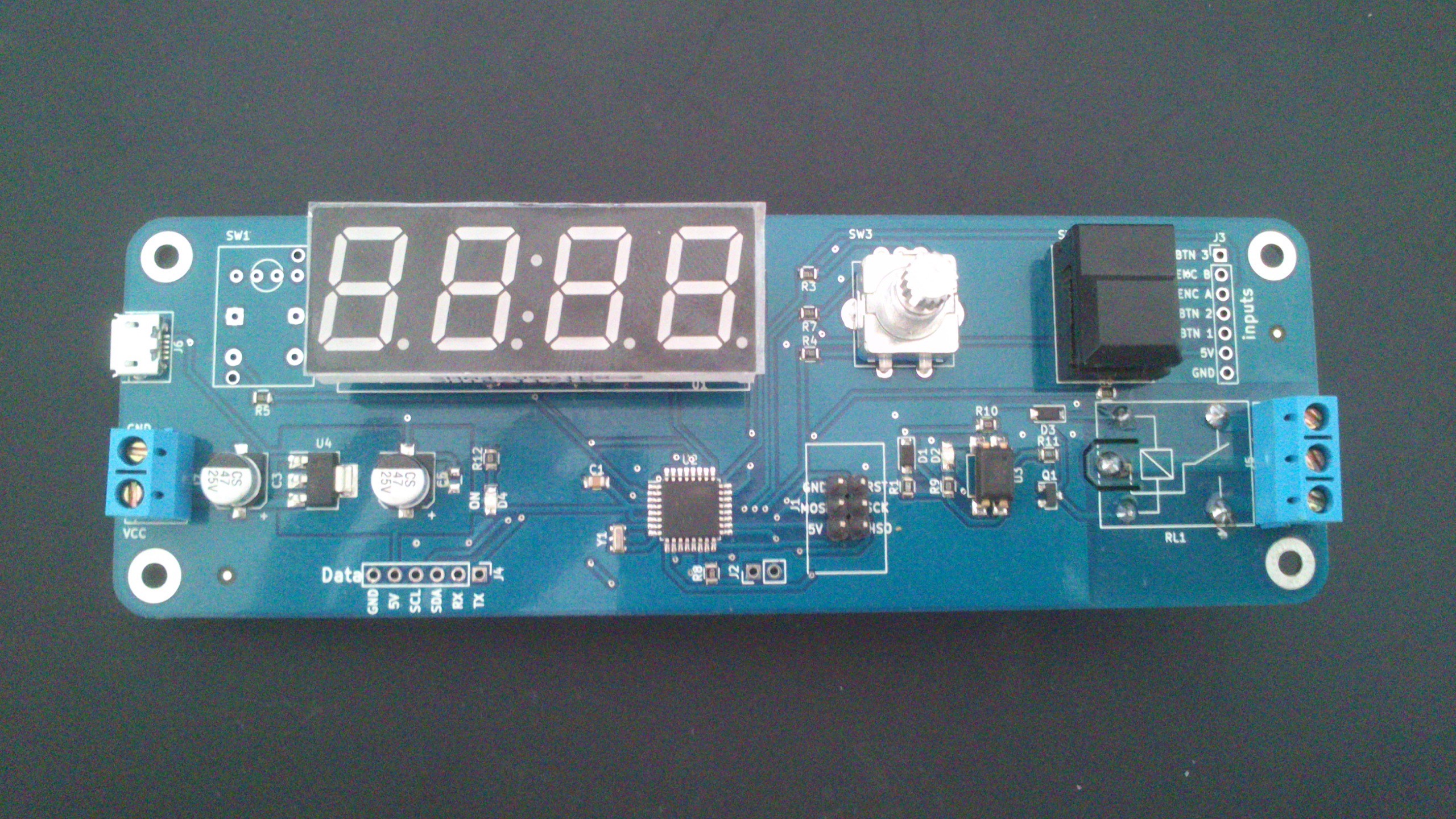 The finished timer. It just lacks the encoder button.
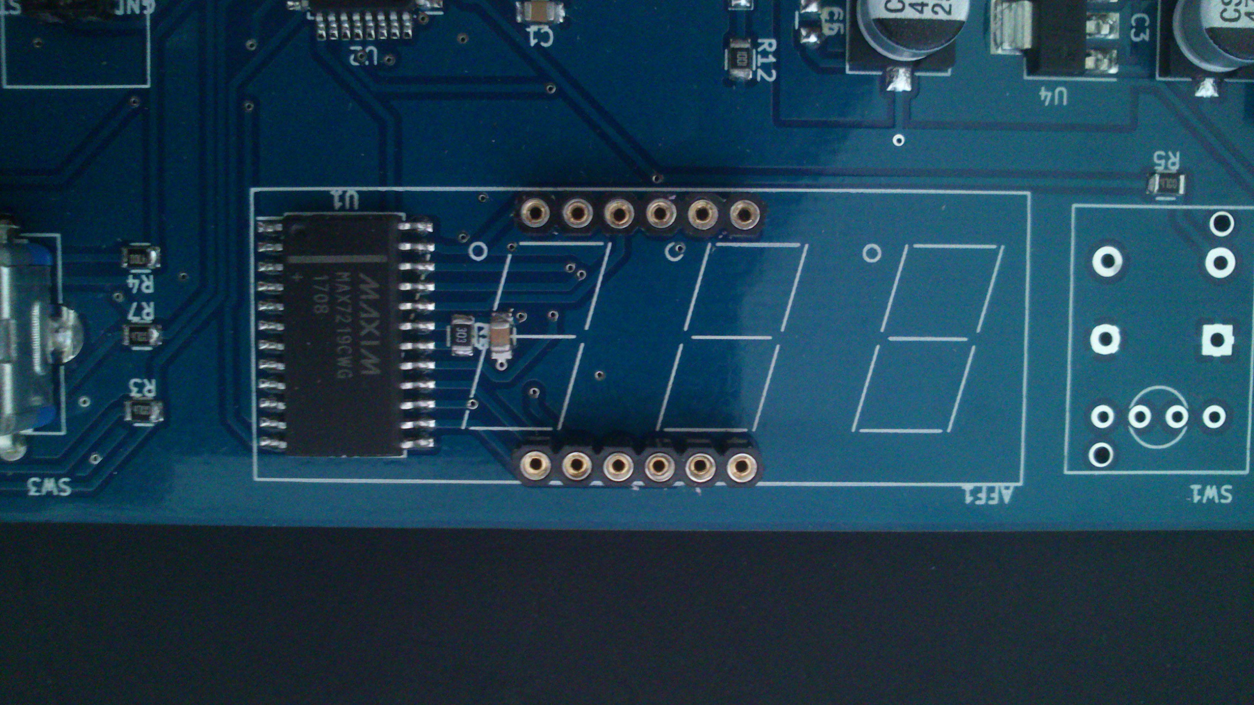 The C2 capacitor and the R2 resistor. Very close components, with the same index, I understand they swapped them. But i would have preferred they didn't! :)
Some considerations about the design, with boards in hand. Even if I tok some time to think about the depth of the trough holes components, it appears that the relay is much more high than the display, button and encoder. I had to mount it on the bottom, to have everything comming at the right level once it will mounted in a printbox.
Using a Atmega8 was maybe not an idea that good: I program the fuses so there's no bootloader, but the program uses almost all the memory on the board, so there's no more room for someone to expand it to suit his needs. I'm not sure the price difference between the Atmega8 and the Atmega328 is worth it. The footprint being the same, maybe I'll change it...
Discussions
Become a Hackaday.io Member
Create an account to leave a comment. Already have an account? Log In.