Connecting the wires
I was very happy that with combining the modifier key lines, I get to 19 distinct wires needed. Exactly the amount of wires I have left on my microcontroller. Phew...
Most of the soldering is now finished:
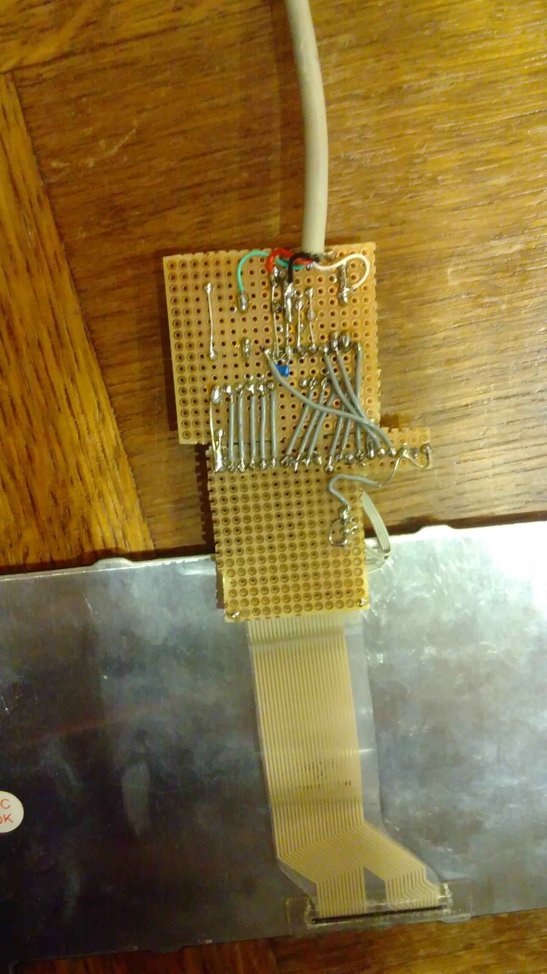
which yields the following schematic:
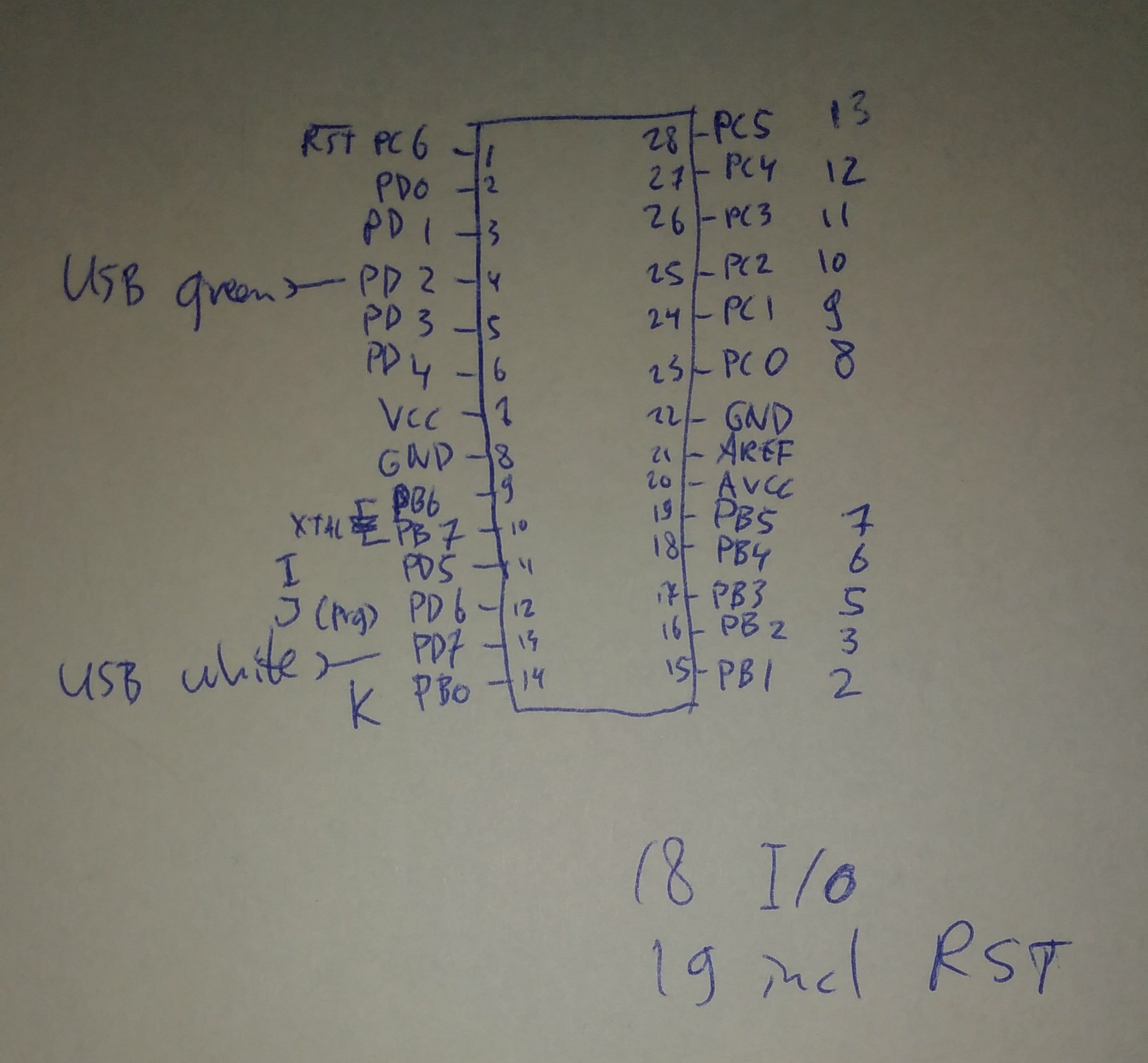
The RST is reserved for wire number '4', because that's the least interesting wire from the keyboard. When I find out how to configure the ATmega8 to use it as PC6 I can use that once. PD0..PD4 also still need to be connected.
Software
I baptized the software project 'AnyHardKeyboard', or AnyHKBD, of course referring to the android's software counterpart that can do many keyboard layouts. More on the USB hardware is in the first log. There I mentioned that the basic software is working. In it's current state it reports itself as follows:
[84822.027766] usb 4-2: Product: AnyHKBD
[84822.027770] usb 4-2: Manufacturer: ronaldteune
[84822.037987] input: ronaldteune AnyHKBD as /devices/****/input/input178
[84822.098920] hid-generic *****: input,hidraw4: USB HID v1.01 Keyboard [ronaldteune AnyHKBD] on usb-0000:00:12.1-2/input0
Time for a small software test with the (almost) full hardware. I'll go for pulling wire K down and then checking PC1,2,5 which should give K, M, J. After one retry (I should really pull wire K down, else it doesn't work...) I have a keyboard that's working! Phew, the 180 ohms of the keyboard is enough to pull the uC inputs to low. It's really funny to have real letters appear on the screen from a real keyboard, with some strange handmade PCB in between... This letters I have typed with my new keyboard as a proof ;-) jkmjmkmjkmjjkmmj
The software can be found here: anyhardkeyboard.tar.gz. It needs cleaning up (it's based on the slideshow presenter) and it needs matrix scanning code together with the debouncing that's already in. I can make it up myself, but have found this line of projects as inspiration and for me to perhaps not make the same mistakes. It's Arduino-based however, so it'll need a little rewrite.
Final words
This makes the first big hurdle almost being taken. I allowed myself to start looking into the DVI-LVDS circuitry after finishing this one (to prevent myself from buying stuff that I'll never use because more complicated things need to be solved - like that time when I wanted to create my own open source Atmel based, non-arduino, OBD2 adapter...) I'm hoping a lot that my TFT is compatible with an off-the-shelf eBay adapter...
Discussions
Become a Hackaday.io Member
Create an account to leave a comment. Already have an account? Log In.