 ziggurat29
Summary:
- Hooked up IR detector to interim test MCU
- Started implementing basic framework for decoding IR signal
- Observed quantifiable events to verify low-level assumptions and implementation
It looks pretty good so far; much more decoder implementation to do.
Deets:
I am currently waiting for more hardware to arrive: the 'Blue Pill' board and the printer itself. Since the results a couple days ago of the otherwise delicious Vishay detector module were not as perfect as I had hoped for -- but still promising -- I was eager to do some further experiments to refine my assessment of the challenges I'm still up against.
I have on-hand a dev board, the 'Nucleo', which has a different processor than the Blue Pill, but it is representative enough to be valid to do work on. I can configure it to run at the same 72 MHz as the Blue Pill, so all my timing parameters should port over as-is.
I am implementing the demodulator using two peripheral resources:
- an EXTI line; basically a GPIO input, with interrupt capability. This is wired to the Vishay detector. For the time being I set it to interrupt on both edges. (bit I will probably change that)
- a timer, TIM4, which I will use both as a timing measurement component and also as a timeout/event generator.
I also configured a GPIO as an output, which I simply twiggle at certain points in the code. This allows me to use the second scope trace to know where in the received signal certain parts of my code are being executed.
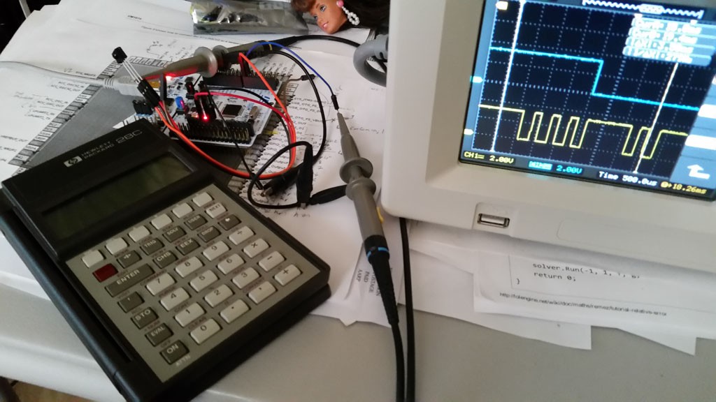
Obligatory bench shot:
OK, I mentioned two candidate approaches to demodulation in the last post. These were to work-around a deficiency in the detector during the initial signal reception. The first involved masking off processing for a period of time, then proceeding with decoding once the signal was believed to be stabilised, and the second involved decoding backwards from the end of transmission, instead of forwards from the front as a sane person would do. Being inclined towards insanity, naturally I planned to do the second. But the next morning I had a clearer head and decided to give Occam's Razor a KISS, and keep it simple until I could prove this entity needed to be multiplied out of necessity.
All that being said, my current approach now consists of:
- a state machine
- an IRQ handler for timer timeouts, and some APIs to set/cancel arbitrary timeout periods
- an IRQ handler for signal transitions
The state machine state currently include:
- 'hunting', which is looking for a period of continual silence. This is used to sync the machine with the signal. The spec dictates the stop condition of 3 half-bits of signal silence, so I use 2 half-bits in my implementation. This will let me validly detect any valid transmitted signal, and give me one half-bit time of fudge factor for timing jitter/overhead/etc.
- 'begin', which means the receiver is ready to start detecting. Ostensibly this is entered after a successful 'hunt' has completed.
- 'start', which is the mask-out period where the start bits come in. As mentioned, normally they would be received as distinct pulses -- and sometimes they are -- but the Vishay device has a tendency to at times merge them together (I think I've noticed some patterns, but more on that when I have done more experiments). Since I've been lucky that so far the observed merging happens only in the 'start' bits, which convey no information (well, other than one bit of information 'start happened'), I should be able to ignore signal during this period.
- 'accum', which is the accumulation of incoming signal transitions to build a datum.
Parts of the machine are implemented in the GPIO interrupt handler, and parts in the timeout handler.
I started out prescaling the 72 MHz clock by 2197 to yield a 32771.96 Hz clock, which is pretty close to the ideal 32768, thinking that this would make some of the coding easier, but I later noticed that some of my timing computations involved periods like 3.5 clocks, so I decided to divide by 1099 to make for a double-rate 65514.10 Hz clock. Then I can resolve those half periods when I want them. (I want them for when I want to sample in the middle of a burst, but maximize robustness against jitter, these bursts are pretty short in duration). As mentioned, the timer is sometimes used to trigger an interrupt on overflow, and sometimes used to measure durations by way of the current counter value.
The GPIO interrupt handler is currently set up to interrupt on both edges. Why? Just initial experimentation. I think I will wind up only using the falling edge in the end.
Currently, what I do is this:
- upon entering the 'hunt' state, set the timer to expire after 2 half-bit times. any edges detected in this state will reset the timer. If the timer times out, then we conclude that we are between transfers, and switch to the 'begin state'
- in the 'begin' state, if we see a falling edge, we interpret that as the start of transmission by way of the first burst. We set the timer to expire 3.25 half-bits later. This means that we expire once all start pulses are out-of-the-way, and in the middle of the burst if the first bit is a '1', or silence if it is '0'. The 0.25 half-bit delay sampling point should clear us from timing mismatch as much as practically possible. Any signal transitions during the 'begin' state are ignored. (I might wind up counting them for QA purposes later, though). Once the timeout occurs, I sample the signal level to 'synthesize' a signal transition that would have occurred beforehand hand pulses not been merged (if they even were, it only happens sometimes). This will transition to the 'accum' state. The timer is reset and a new timeout is set to be 1/4 half-bit past the last expected bit period. When this timeout occurs, we know the data transmission has finished, and that we are in the stop bit period. I chose 1/4 half-bit period to give a little insurance against timing jitter, a little time for any processing overhead, and plenty of time for 'hunt' to succeed between transmissions.
- in the 'accum' state, signal transitions will clock in bits. I have not implemented this yet. Also, when timeout occurs in this state, we conclude that the data transmission is completed, and can do parity checks, error detection/correction, and emit the received byte to whatever part of the system will be consuming it -- probably a queue with some sort of semaphore indicating 'data available'. I am expecting to use a scheme where I measure the current time (the timer's counter value) and depending on how long it was since the last transition, and whether the last bit is a 1 or 0, determine what this bit is. This should work because there is always 1 burst per bit period. This will make for 4 timing windows, which I have not yet calculated (4 because there are two bits -- the previous known one, and the current one being decoded).
As mentioned earlier, to help debug/validate my code, I also provisioned a GPIO line which I twiggle and can observe on the scope's second channel relative to the received signal on the first channel. Following are some traces that depict what I have described above. Channel 1 (yellow) is the Vishay module's output (and input to the board), and Channel 2 (blue) is the GPIO that I twiggle in my code at places of my choosing.
Overview Trace:
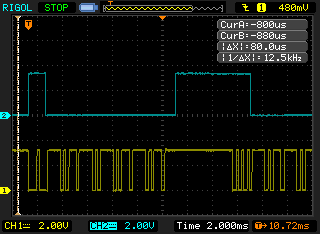
There are two data transmissions shown here. I set the code to set the GPIO high when I first detect signal, and when I have timed out at the expected end-of transmission. I set the GPIO low when I have exited the 'start' state/entered the 'accum' state. You can't see the 'hunt' state, alas, because I only have a 2-channel scope :(. But, since the board resets with that line low, you can at least see the entrance to 'start' in the first capture, and just take it as read that the other's work the same way. Anyway... in this trace you can see the chunk of time where the start bits are being ignored (the high time on the blue trace on the left), and where the accum state starts (the low time), and where the data transmission is expected to be over (goes back high), and the same process for the next trace (but not being able to see the intervening hunt state change to the start state, alas, because there are no twiggles to differentiate them). Also noteworthy in this capture is that the first transmission has merged the first two bursts and the next two bursts. The second transmission demodulates ideally, with all the bursts being distinguishable as one would prefer.
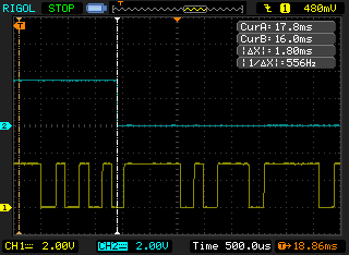
The next capture is a zoomed in version of the start of the first transmission:
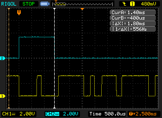
Again, in this transmission the first two bursts of the start period are merged, and the last burst in the start period is merged with the first data-conveying burst. Cursor A shows where the timer times out (via the debug GPIO, shown on baby blue Channel 2), which is meant to be in the middle of the bursting period if the bit being transmitted is a '1', as is the case here. The computed ideal time for this is 1.388599 ms, and scope say 1.4 ms, so: great. This sample point will be in the middle of the bursting period if the first bit is a '1' (as it is here), or in silence if it is a '0'. Since we know that at this point we are meant to be 3.5 carrier cycles into the bit period, we know where we are and what signal we are supposed to have, so we can set up the decoder into a state as if we had a properly demodulated start bit period. You'll see later, but first I want to show the end of the signal for this transmission.
End of Transmission:
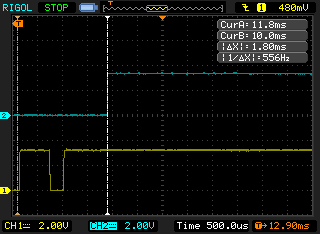
This is visually boring, but this is where the timer expires at the end of the 'accum' state. Cursor A is positioned on it, and shows 11.8 ms, which is close enough with the computed ideal of 11.74926 ms. As mentioned before, this is 1/4 half-bit time out from the end of the last bit's period, and into the beginning of the stop period's quiescence. In retrospect, I don't need to extend into that here, so maybe I'll alter the code later. (Because the last transition, if the last bit is a 0, will end 1/2 half-bit time before the bit's period ends, anyway.)
When this event occurs, we transition back into the 'hunt' state, looking for contiguous silence, and then transition into 'begin' where we look for the first burst in the next transmission.
Here is the start of the next transmission:
As mentioned before, I didn't bother to reset the debug GPIO line going out of 'hunt' (I added that state later in the development), but take it as read that 'start' does begin with the first falling edge. The timer expires in the middle of the first burst of the data-conveying portion of the signal.
In this transmission, we were fortunate in that all the bursts were demodulated correctly, and we can see all the individual bursts in the start period (the first three). We can also see that the timeout in the 'start' state does hit in the middle of the first burst (if it is for a '1' bit), so: great.
Moving forward with this approach is warranted, I think.
Onwards:
I'm still waiting to receive the Blue Pill and the actual printer. The Blue Pill should be here in a few days. There is a bunch of coding I need to do on the decoder, and I have a great surrogate dev board with my Nucleo. Really, my great risk now is getting those parts in before I'm ready to receive them.
It's holidays where I am now, and parties will compete for attention, but I do feel compelled to get data decoded correctly. What I am hoping to do for my next test is to:
- decode data
- accumulate statistics of successes, signal loss, parity errors, recoverable errors, etc. Maybe convey them via some LEDs on some GPIOs, and fiddle with range and whatnot to see how reliable this thing is without needing to do a scope trace every time.
- build the next layer of software for this part, which makes this look like an input stream of bytes. Something like a notional /dev/irin if you like. Either way, close the book on bitfiddling with IR, and get on with building up the rest of the system
//end
Discussions
Become a Hackaday.io Member
Create an account to leave a comment. Already have an account? Log In.