 ziggurat29
Summary:
* My Blue Pill dev board(s) arrived; now I have 6
* The board had some software protection kookiness that had to be worked around (hence 'Red Pill' reference)
* I got the board working with the toolchain
Now it's time to add some higher-level system functionality; probably UART (and maybe USB serial for debugging), circular buffers, and event notification.
Deets:
Today, my 'Blue Pill' 'STM32 Minimum System Development Board' came in. Interestingly, both the 5-pack I ordered domestically, and the 1-unit I order from China. I guess it came on the fast boat from China this time. So now I have plenty to destroy in the process of this project.
The board uses a STM32F103C8T6, and it was straightforward to set up a STM32CubeMX project with that processor. I went ahead and declared assignments for the very few hardware items on the board: A jumper for BOOT1, a push button, an LED, the USB, and the two crystals (I'm a little surprised they splurged for to crystals).
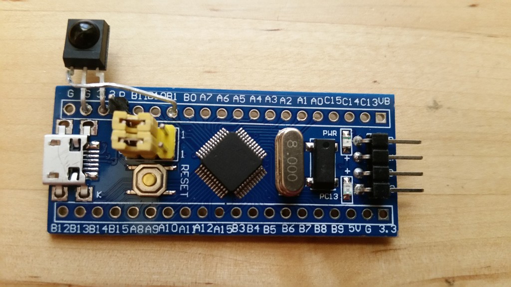
Now I have to decide where I'm going to put my hardware. Looking at the pragmatics of physical placement, I have decided to put the demodulator on PB1 because I should be able to bend the pins on the Vishay TSOP-4133 and connect it there next to where power is also available. I've pretty much decided to put the printer on UART2 using PA0,1,2,3. I believe the printer uses hardware flow control, so I wanted the RTX/CTS lines, and UART1 has those tied up with USB. Anyway, UART1 is used for the bootloader, so I just as soon leave that free for now.
Next I wanted to do an initial test drive of the toolchain. Immediately upon connecting the board (via USB, which also supplies power), I noticed /something/ enumerating on the system. Hmm. That means the chip is not blank. The thing enumerates as "Maple 003" vid/pid 1eaf/0003. I don't know what this is, the vid/pid don't lookup to anything known, but I am guessing that it is a bootloader that is meaningful for the Arduino guys. Interestingly, the board from China does not have this, it just has a 'blinky' application running. Another minor difference is that the board from China has an amber led, whereas the ones shipped domestically have a red led.
There was a little challenge, though, in that I could not program the device initially. I started up "ST-Link Utility", and it complained about "data readout protection".
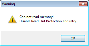
I see how the game is played! Who knows why they turned on DRP, but fortunately, it turns out that this is reversible. Using the ST-Link Utility, and navigated Target,Option Bytes..., select 'Disable Read Out Protection'.
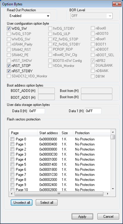
Option Bytes before:
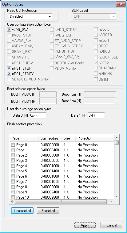
Option Bytes after:
FYI, the board from China did not have this challenge, so your mileage may vary. Also, apparently you can do the same from gdb/OpenOCD directly with the command:
monitor stm32f1x unlock 0
This resets the protection and erases flash. So he board has taken the 'Red Pill' and gone back into my Matrix, and now I have a blank board.
Tool Time:
I started up the System Workbench, but I could not get the debugger working. The complaint was 'unable to erase flash'. I fiddled with the openocd configuration file, but to no avail. In the end I hazarded a guess that the NRST line needed to be connected, since that was notably missing from the 4-pin connector at the end of the board relative to my other boards (that, along with SWO). NRST is available on the side, though. I soldered a 1-pin header on that, and connected it, and then things were working.
I still suspect that there might be some clever openocd magikry that can be put in the config file, but I don't know what it is. I'm up now, so I'm not going to look further (at least at this time).
UPDATE: I did figure out how to avoid needing the NRST line. It's a bit convoluted. First, you must have a 'debug' configuration to edit. If you start to debug, it will fail, but in the process you will have one to change. Then select project properties, and "Run/Debug Settings". Select the newly configured debug setting (or just skip to this step if you already have one. Then select 'Edit'. This will open a new dialog, and select the 'Debugger' tab. Down the page, you will see 'Show Bootloader Options' that will expand things further (it will be 'hide' if you've already been here). Once you've expanded that stuff, there will be an item 'reset mode'. The default will be 'connect under reset', bu you will change that to 'Software System Reset'. Tada! What all this means is that a software command is sent over the SWD lines to reset the board at the start of debug, instead of using the hardware reset line.
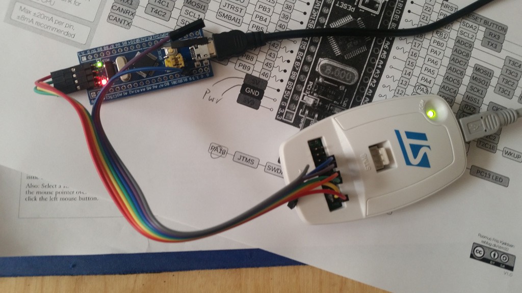
I bent up my detector like this to mount it on the board:
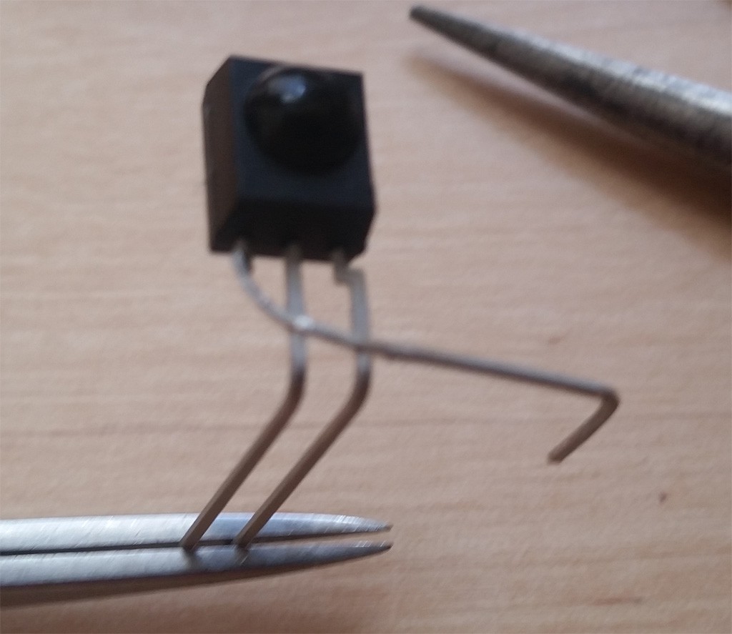
The added NRST pin is a mild annoyance, since it is right in the middle of where the detector line is being routed, but a little bendage of that wire keeps things reasonable safe from shorts.
OK, so I'm back up with the new board!
Next:
Now that I am in the same spot as a couple days ago -- just with the new board -- I can continue work. I need to implement a bunch of system code in advance of receiving the printer unit. I will probably start with UART support. I possibly will also implement USB CDC so that I can have a means of getting debug output as well.
Discussions
Become a Hackaday.io Member
Create an account to leave a comment. Already have an account? Log In.