 jaromir.sukuba
This circuit exploits two parameters of key components - temperature dependence of lightbulb and hysteresis of relay - which are usually overlooked.
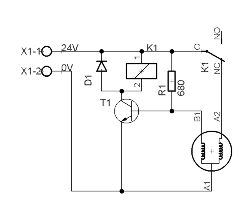
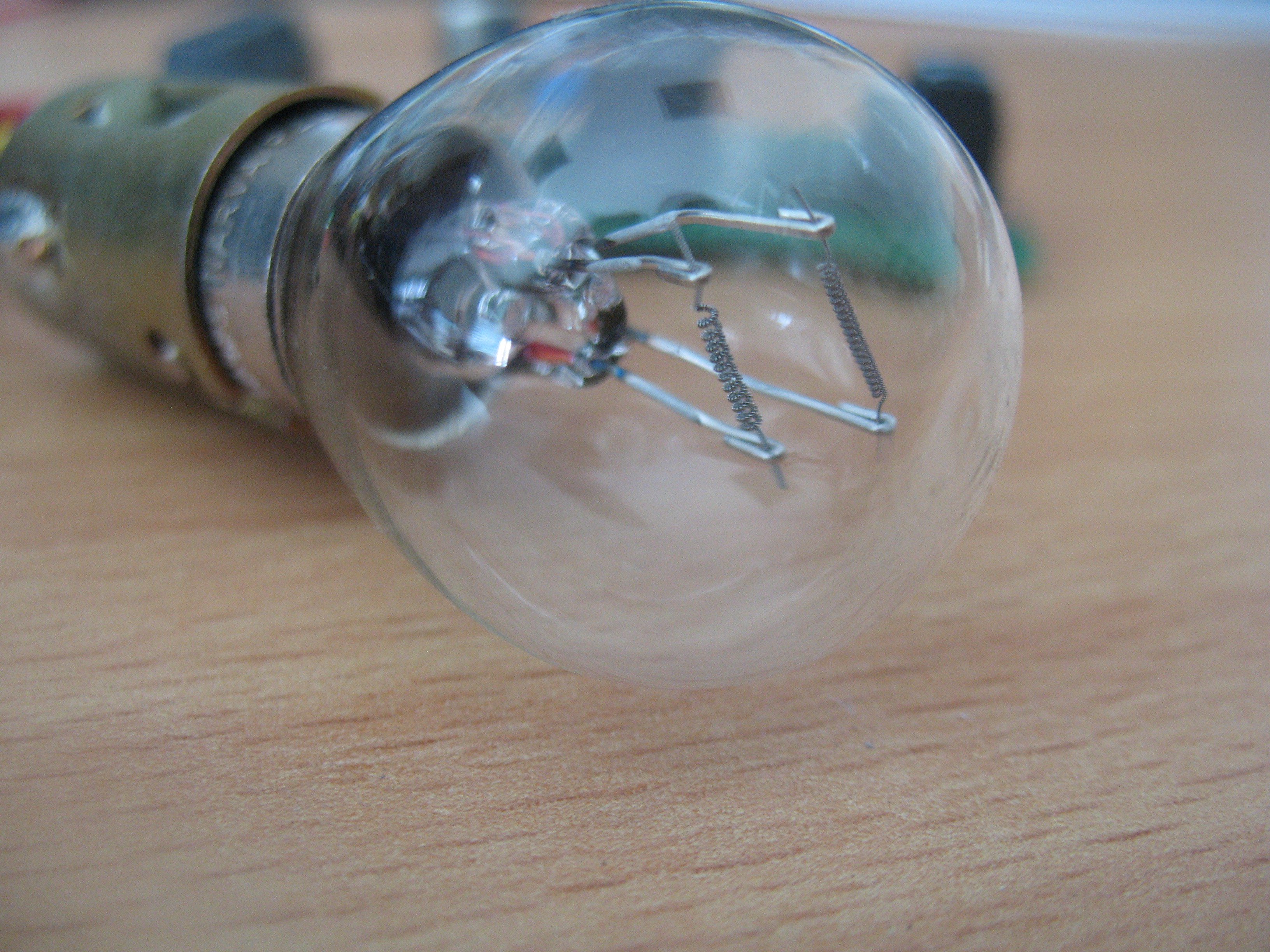
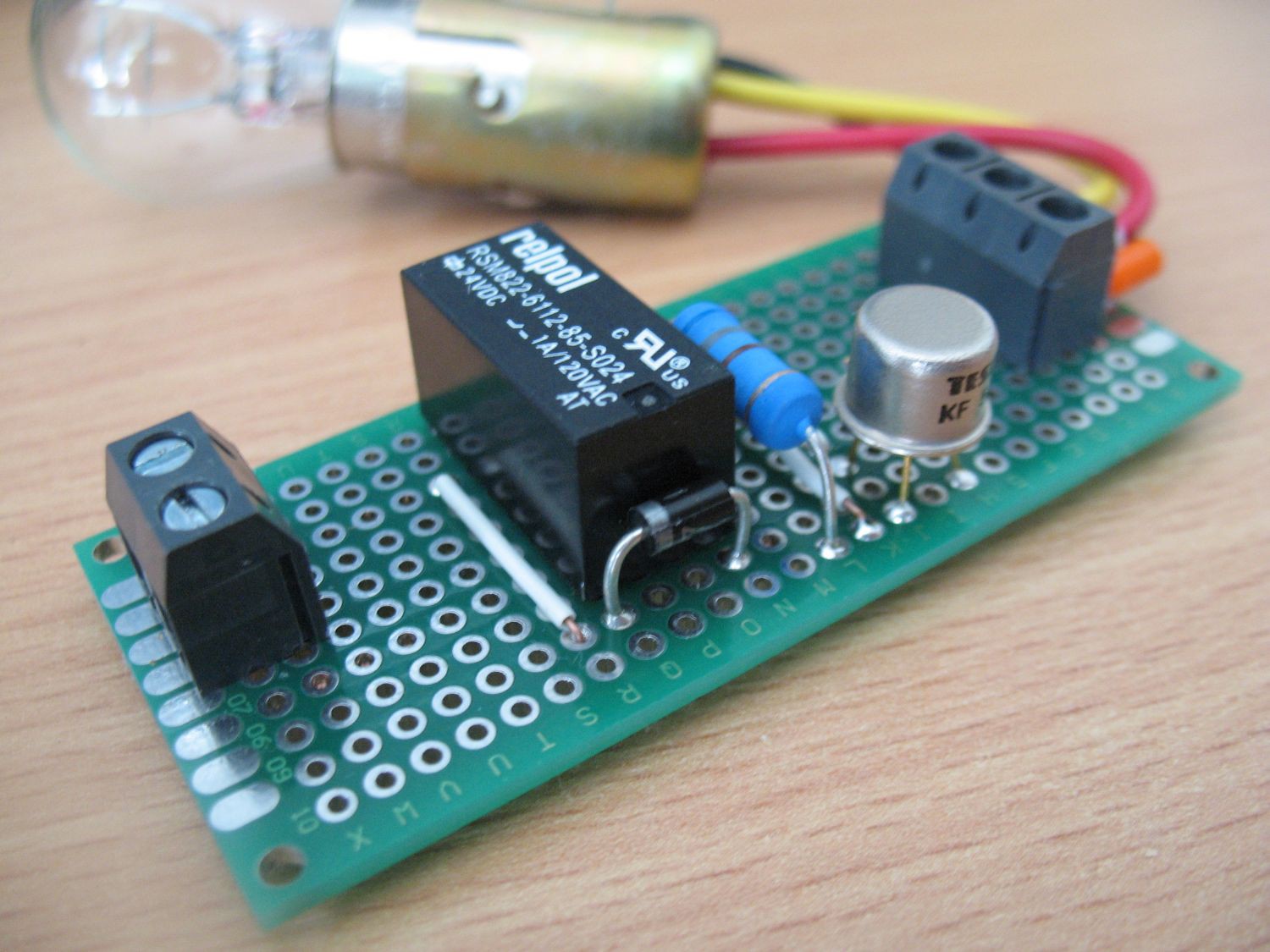
When power is applied, relay is not energized, current flows through NC contact and lightbulb goes on. Notice the lightbulb has two filaments - designed for 21/5W car lights
Here you can see voltages on base of T1 (yellow), collector of T1 (blue) and voltage on 21W filament of lightbulb (purple).
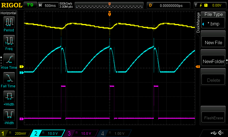
As current flows through the 21W filament, the another one heats up too.
Its resistance rises, so voltage on voltage divider - formed by R1 and
filament - starts to rise. This causes transistor T1 to open, collector
current increases and voltage on relay coil increases too. When it
reaches some threshold value, relay engages, NC contact is open and
current stops flowing through the 21W filament. Temperature of 5W
filament decreases too, so the voltage on base of T1 decreases. On the
other hand, it takes a while for the filament to cool down and as this
happens, collector current falls down accordingly. Relay doesn't switch
off immediately, but exhibits some degree of hysteresis, so it takes a
moment to switch off. This effect and thermal mass of the filament is
the main contributor to switching frequency being in range of 1Hz.
Not how fast the lightbulb heats up (quick rise of T1 base voltage) and cools down slower. When I decrease voltage from 24V to 18V, the voltage rise is much slower - because temperature of filaments reaches lower value - so also collector voltage doesn't have such as high voltage swing. Because the heat-up time is longer, the on/off ratio and frequency changes too. 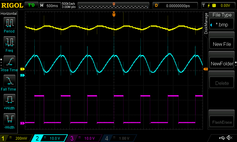 And some more photos:
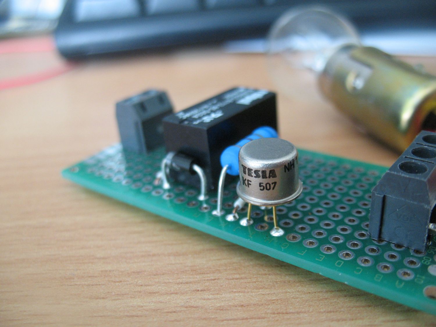
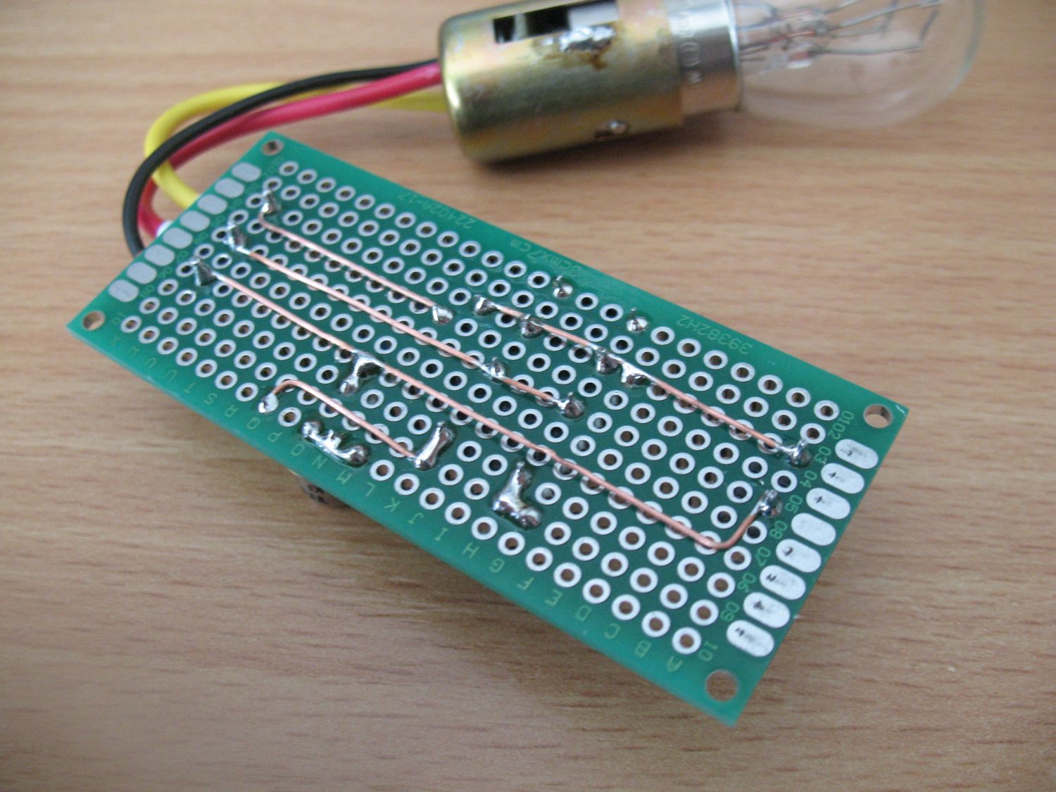
Discussions
Become a Hackaday.io Member
Create an account to leave a comment. Already have an account? Log In.