 doctek
The accelerometer was removed because of shorting under it, but now it was time to re-install it. I cleaned up the solder pads for the accelerometer - both the ones on the accelerometer itself and the ones on the PCB. A short length of finely stranded wire with a drop of liquid flux on it made a great solder braid for these tiny pads. The accelerometer was placed carefully back on the pads for a quick trip to the toaster oven for reflow. I was hoping there was enough solder left to make the remount work.
"Hope" is never a good strategy, and, indeed, the accelerometer would not answer up on I2C. (Although it did at least stick to the pcb.) Hooking up the scope verified that. Either the SDA or the SCL, or both, were not connected. As a last hope, I used a straight pin to put a tiny amount of solder paste on the side of the accelerometer with pins 1 and 4 (yup, that's SDA and SCL) and a bit of liquid flux everywhere else. Then into the toaster oven again. Success! I2C queries now got correct responses. Picture shows the board all together with the accelerometer and the Interrupt 2 jumper (described next).
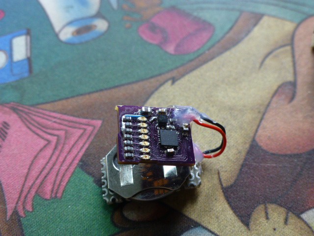
With I2C working, I could configure the accelerometer, but for it to be useful, the interrupt needed to work. Without trying anything so complicated as configuring and triggering an actual interrupt, I was able to test the operation by changing the polarity of the interrupt pin using the I2C bus. Doing this, I quickly discovered that the Interrupt 1 pin did not seem to be connected either! Rather than trying another repair, I used a stand-by scheme I had planned. Interrupt 2 was pinned out to a via on the board which could be routed to a via in the Interrupt 1 trace. So I verified that Interrupt 2 could change level under I2C control, then shorted the vias. Now Interrupt 2 was connected to the ATTINY84. Yahoo! With thanks to STM for their design, I found that all functions that Interrupt 1 could perform could be performed by Interrupt 2. The accelerometer was now ready to use.
Discussions
Become a Hackaday.io Member
Create an account to leave a comment. Already have an account? Log In.