Close
0%
0%

Bicycle Tour Pal Equipment Based on Bluetooth

For a bicycle “tour pal”, the greatest demand is safety during riding besides adding various cool equipment for his/her bicycle, such as how

Similar projects worth following
For a bicycle “tour pal”, the greatest demand is safety during riding besides adding various cool equipment for his/her bicycle, such as how to let vehicles and pedestrians behind know his/her steering direction in advance; lighting during night riding; current ambient temperature and humidity; how to know his/her correct geographic location in field environment, etc. Thus, the bicycle tour pal equipment based on Bluetooth communication emerges.

[Functional Introduction]

With the knapsack as the carrier, the product utilizes Bluetooth technology to realize the communication between the head control end and knapsack steering indicator. Meanwhile, the head control end is dismountable. After the tour pal gets off the bicycle, the head control end can be still bound on the arm for using continuously. GPS positioning is also embedded in the system. Its specific functions include: steering indication of bicycle, head lamp, ambient temperature and humidity detection and GPS positioning.

Components:

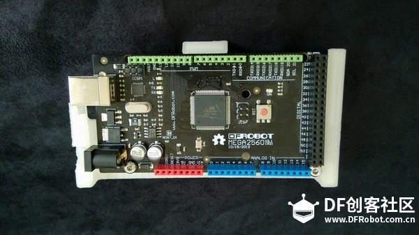
DFRobot Mega 2560 V3.0 (Arduino Mega 2560 R3 Compatible) *3

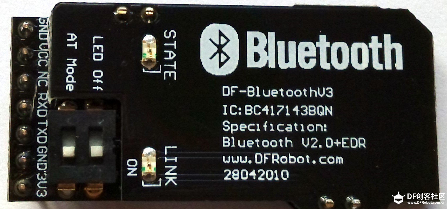
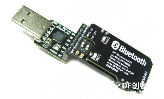
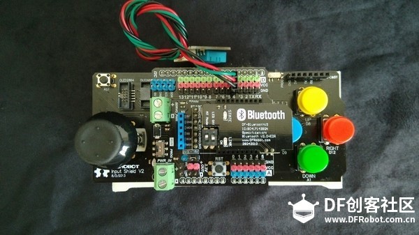
Bluetooth 2.0 Module V3 For Arduino *2

Gravity: IO Expansion Shield for Arduino V7.1 *2

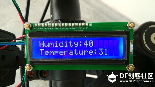
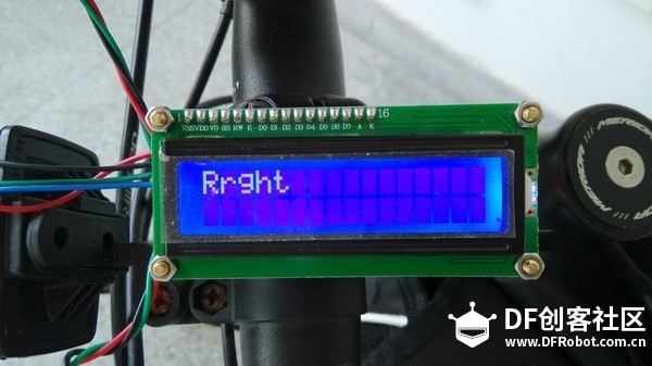
I2C 16x2 Arduino LCD Display Module *1

Input Shield for Arduino *1

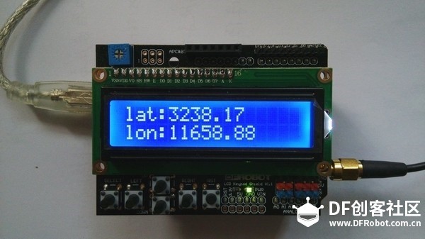
DFRduino GPS Shield For Arduino (ublox LEA-6H) *1

Digital RGB LED Strip 60 LED - (3m)(weatherproof) *1

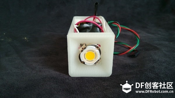
10W Super Bright LED - Warm White *1

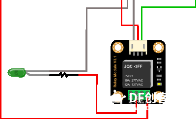
Gravity: Digital 5A Relay Module *1

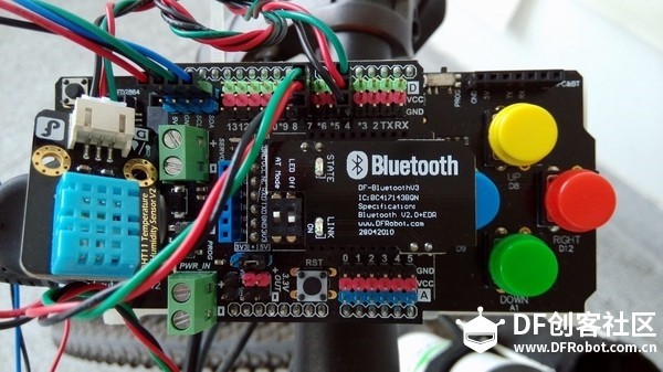
Gravity: DHT11 Temperature Humidity Sensor For Arduino *1

1602 LCD Keypad Shield For Arduino *1

Battery *3

USB to TTL Converter (CP210) *

  • 1
    Printing of mechanical structure

    In this product, we use 3 parts of mechanical structure: steering gear light trough, head handle control end card slot and head lampshade. We use 3D printer to print out its mechanical structure, specifically as follows:

    Steering gear light trough (filling rate 30% +Brim)

    Steering gear light trough (filling rate 30% +Brim)

    Handle control end (filling rate 50%+BRIM)

  • 2
    Installation of Circuit Structure

    A. Setting of Bluetooth communication module

    (1) Switch Bluetooth module to AT mode: As shown in the figure below, the module has a 2-bit dial switch. Switch No.1 LED Off is the LINK lamp switch and may switch off LINK to save power. LINK lamp is on when the switch is pulled to ON and LINK lamp is off when the switch is pulled to the other end; switch No.2 AT Mode is the AT instruction mode switch. The module will access AT instruction mode when the switch is pulled to ON, and the module will exit AT instruction mode when the switch is pulled to the other end.

    (2) Connect to USB to Serial module: Insert DF-BluetoothV3 Bluetooth serial port module on the USB to Serial port as the figure below:

    (3) USB to Serial module needs to be installed with a drive program. After the drive program is installed successfully, a serial port will be displayed in the device manager, i.e., Silicon Labs CP210x USB to UART Bridge(COM15) in the device manager as shown in the figure below. This COM port is used to configure the Bluetooth module.

    (4) Configure the Bluetooth module through the serial port instruction. We need to use the serial port monitor here to complete configuration. Many types of serial port commissioning software can be used to do so. Of course, you may also use the serial port monitor attached with Arduino IDE. We select the serial port monitor attached with Arduino IDE here to complete configuration. Firstly, switch on IDE and check whether the serial port is displayed. We select COM4 here. Switch on the serial port monitor interface, set the Baud rate 38400 and select “line break and enter mode” (Both NL&CR).

    [Note]: In AT mode, the Baud rate is defaulted as 38400, which is unrelated to the Baud rate set during communication.

    After the setting is completed, input “AT” (case insensitive) in the serial port to test whether the Bluetooth module is connected with USB serial port. If so, “[OK]” will be displayed. Likewise, you may input relevant AT instruction in the serial port to complete configuration immediately.

    (5) Set master-slave module. In case two Bluetooth modules are paired, one shall be set as the master module and the other one shall be set as slave module.

    B. Install circuits of steering gear

    Cut two sections with appropriate length in Colorful WS2812LED light strip, and install them in the printed steering gear light trough, and extract the connector with three Dupont lines. Note: During welding, welding spots are near. Do not connect lines mutually.

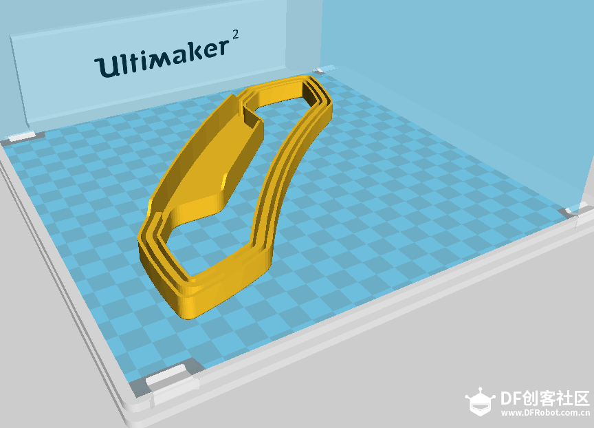
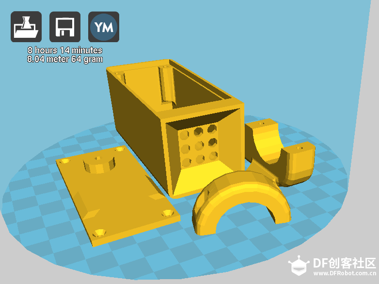
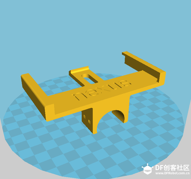
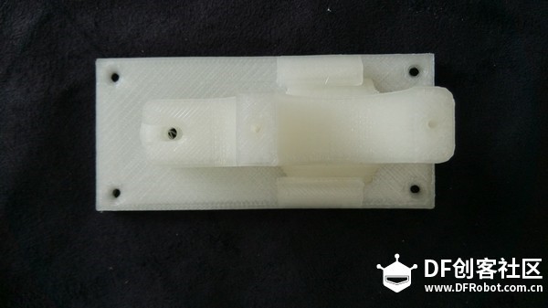
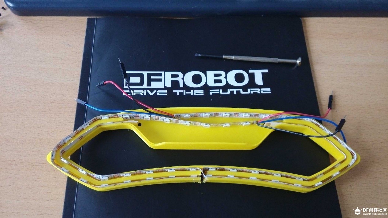
    Then, insert the Dupont lines of LED at both sides on the digital port 8.12 of slave control mdule respectively, and insert the slave Bluetooth module on the Bluetooth interface. As shown in the Figure below, place the slave control end of Bluetooth in the interlining of knapsack.

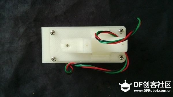
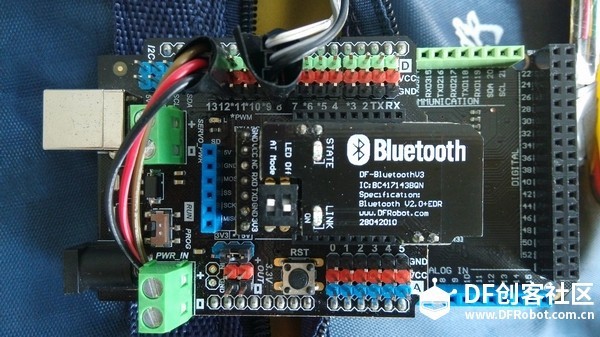
    We place the steering indicator outside the knapsack, and fix it on the surface of knapsack through two sets of nylon screws. As shown in the figure below, the circuits at the slave control end of Bluetooth are installed successfully.
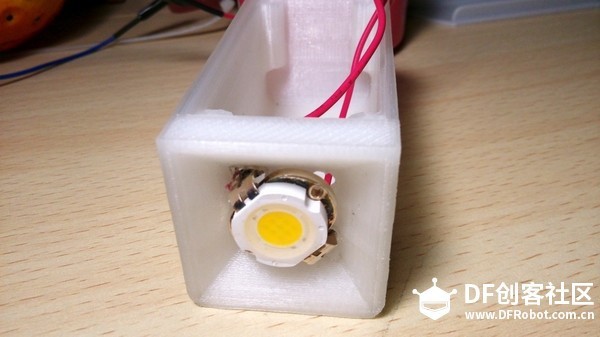
    C. Install head lamp

    As shown in the figure below, install the 10W high-light LED on the printed part of head lampshade. The LED pin shall be as shown below (the end with notch is negative pole). This type of high-light LED includes 9 LED arrays. With illumination intensity of 500LM, it can serve as ordinary lighting source or strong light source of robot.

    Connect it with the relay and battery. The specific connection is as shown in the figure below.

    3. Extract one end of 3-core Dupont plug from the hole at the lampshade side, cover the lampshade base plate and fasten the screws

    3. Extract one end of 3-core Dupont plug from the hole at the lampshade side, cover the lampshade base plate and fasten the screws.Finally, fix the lamp part at the front of bicycle head and fasten the head lamp with the fixed part of bicycle head at the lower part.

    Finally, fix the lamp part at the front of bicycle head and fasten the head lamp with the fixed part of bicycle head at the lower part.

    D. Install the circuits of head main control board

    Install the DFRduino Mega 2560 V3.0 controller in the main control card slot of head and fix the main control plate with screws. The position of serial port and power supply port is not taken into account during design, so you shall repair the mold to provide the position for the two ports above.

    After the installation steps above are completed, add input expansion board V2.0 on the main control plate respectively, so we add the control button for the main control end. Add IO sensor expansion board V 7.1 on the input expansion board, so that the modular connection platform is provided for lamp, DH11, LCD display screen and Bluetooth main module, avoiding the complicated line plugging as shown in the figure below.

    After the installation steps above are completed, add input expansion board V2.0 on the main control plate respectively, so we add the control button for the main control end. Add IO sensor expansion board V 7.1 on the input expansion board, so that the modular connection platform is provided for lamp, DH11, LCD display screen and Bluetooth main module, avoiding the complicated line plugging as shown in the figure below.


    E Connect DH11 with 1602-character LCD

    DH11 detects the temperature and humidity at current environment real-timely and displays the value on the1602-character LCD, providing reference for the tour pal. Connect the DH11 with the digital port 4 of IO sensor expansion board, and connect head lamp with the digital port 7 of IO sensor expansion board.

    The 1602-character LCD functions as information display in this product, showing the temperature and humidity values detected by DH11 and state change when the button is pressed. Connect 1602-character LCD with the digital port I2C of IO sensor expansion board. Please note the Dupont line sequence. Do not connect reversely.

    F. Install GPS module

    The GPS function module is a relatively independent unit in this product, so its installation is relatively easy. We realize GPS positioning through overlapping layer by layer with DFRduino UNO R3, DFRduino GPS Shield-LEA-6H and LCD Keypad Shield key expansion boards here. It shall be noticed that GPS gain antenna needs to be installed externally. Otherwise, the positioning is impossible. The longitude and latitude values of positioning will be displayed on the 1602-character LCD to provide reference for the tour pal.

    So far, we have completed installation of all mechanical structures and circuit connection. Then, input code to realize functions.

View all instructions

Enjoy this project?

Share

Discussions

Similar Projects

Does this project spark your interest?

Become a member to follow this project and never miss any updates