The is the first entry in the Global Seer project log. Before I get into the nitty gritty of any actual build I will always engage in bouts of blue-sky thinking about the project in question. For this case, they resulted in 'approximate' platform design in the cover photo (shown again below but with legends this time round). Although it probably will not resemble the final iteration in any shape or form, this flight-of-fancy design does allows me to have an overall view project and points to a direction to head towards...
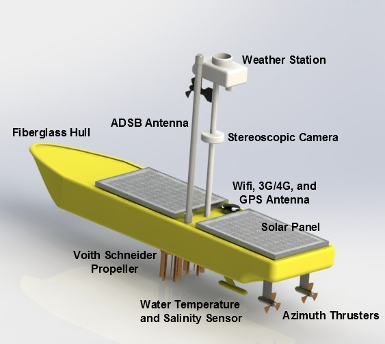
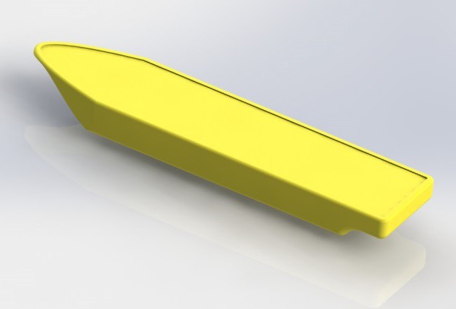
The first target of my blue-sky thinking is the design of the ocean platform. I guess what is needed here is a platform that is compact/streamlined (so that it can braves the storm with relative ease?) and have a relatively large payload capacity. Speed in this case, though preferable, is not really required in this case. From the way I see it, a Global Seer platform will probably be undergoing a long range trek to the destination. Once at the destination, it will only be required to make short distance positional changes to improve coverage. Therefore I went with a rather conventional single hull design (show below) for the platform. As it stands now, the hull from bow to stern has a length of about 1.3m and a width of 308mm. This is largely determined by the size of the sample solar panel that I have got which is 390mm X 254mm . From the deck to the keel is about 150mm. This is determined by the height of the sealed lead acid batteries. More studies will need to be conduced to find out the actual water displacement of the hull, address stability issues and carry out refinement of the keel design.
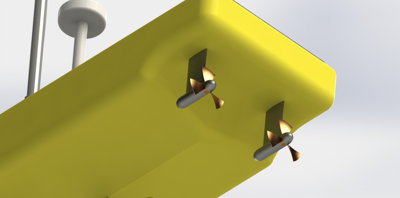
The next choice issue that I will tackle is the selection of a propulsion system. For this case I have opted for use of pair of azimuth thrusters (shown below) as oppose to the traditional rudder system. These are basically motor and propeller pair attached to a swiveling mount. This arrangement is supposed to be more efficient compared to inboard mounted motors as torque lost through a long drive shaft is eliminated. There is increased maneuverability as the thrust can be directed in any direction even in reverse. As the motors are outboard, there is also more space in the hull for various payloads. Two thrusters instead of one for redundancy consideration. Mechanically it is also simpler as the number of rotational coupling through the hull is reduced from 4 to 2. The only case when I cannot think of a clear advantage over a normal rudder is what happens when the swivel mount fails? There may also be issue in the design of the rotational coupling through the hull as there is a need to feed power to the motors.
Another problem that is related to the propulsion system is the issue of position holding/station keeping. Strictly speaking the area coverage of the ADSB signal does not require high accuracy position holding to effect. Even for the purpose of multilateration (MLAT), the determination of the position of an aircraft from the minute time delay (referenced with GPS clock signal) between signal received from it at different receivers, is dependent mostly on the accuracy of the GPS (typical about 10m). However if the Global Seer platforms are placed in a mesh network for communication relay the issue of position holding becomes important. In order to bridge a certain communication distance with as little number of platform as possible, it would be helpful to place the platform just within radio communication range of each other thus requiring highly accurate position hold.
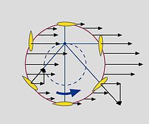
While the azimuth thrusters excel in providing excellent maneuverability, they are very slow to react to fast positional drift. This is because in order to redirect the thrust, the whole azimuth assembly needs to be rotated. While trying to source for a solution to this problem, I stumbled upon a propeller configuration that I think is very ingenious. It is called the Voith-Schneider propeller. A rc version of it is shown below.
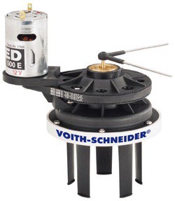
Basically it consists of a series of blades that are mounted vertically beneath a ship. The pitch of the blades are determined by a series of mechanical linkage to the central rotating shaft. The mechanical linkage is implemented such that water is always directed in a certain direction (shown below the direction of force acting on the blade by the water). Depending on the relative position of the of the mechanical linkages and the rotation shaft, water can be redirected in any direction almost instantly. A video animation of its workings can be found here (http://www.voith.com/en/products-services/power-transmission/voith-schneider-propeller-10002.html).
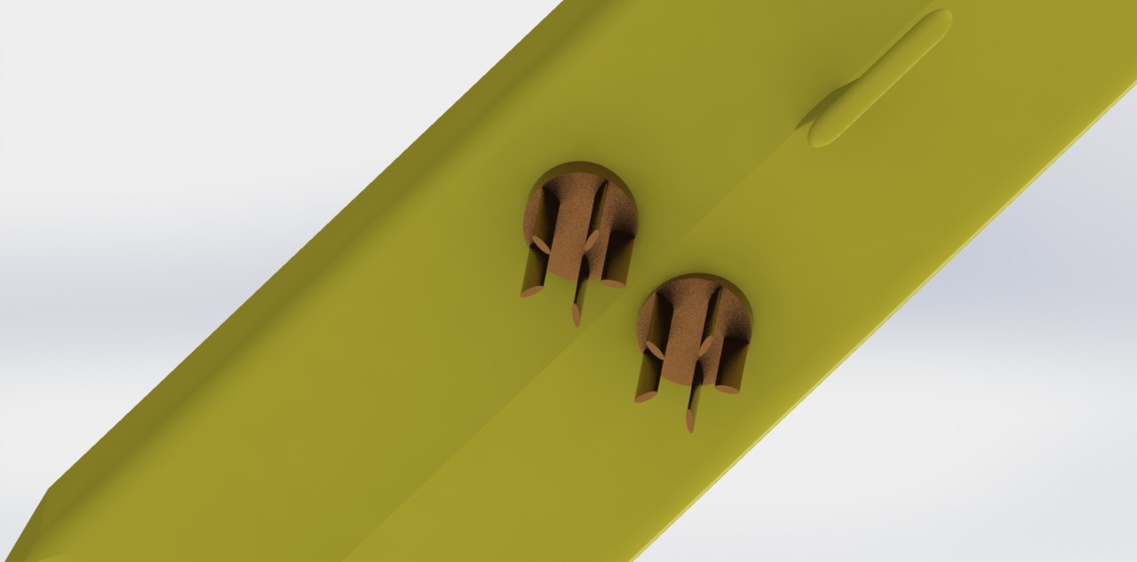
What I have planned is to implement this at the keel near the amidship (shown below). I will try to come up with a design that locks all the blades in the forward direction during long distance straight line sailing such that the blades act as stabilizers. Once at the destination, the blades will be unlocked for position holding.
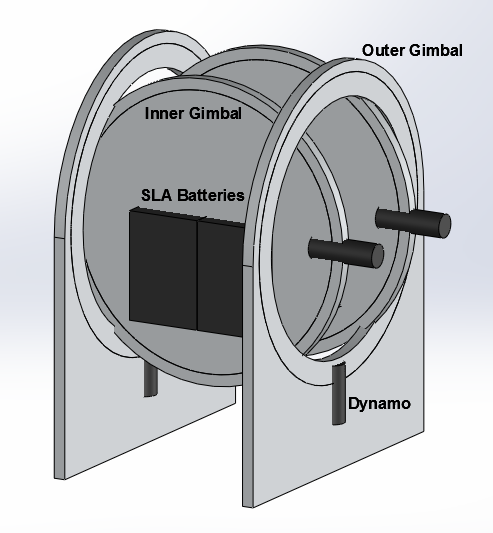
The last of my blue-sky thinking have to deal with the power systems. On the vast expanse of the ocean, two things are in abundance - sunshine and waves. The solar panel kind of address the problem of extracting energy from sunshine. What about the waves? Surely the pitching and rowing motion of the platform can be tapped for energy. An idea (shown below) popped into my head. The heaviest component the sealed lead acid (SLA) battery can be mounted in free moving gimbals. Because the battery are mounted off center in the inner gimbal, it will always settle in a direction point downwards. This movement can be used to drive dynamos to augment the power generated by the solar panels. One possible issue is that the whole contraption takes up a lot of space. More design work needs to be done here I suppose.
Discussions
Become a Hackaday.io Member
Create an account to leave a comment. Already have an account? Log In.