Close
0%
0%

Converting a Robbe Starion to Furibee F36 TX

Converting an old Robbe Starion RC transmitter to fly my Furibee F36

Similar projects worth following
I used to have an old 40 MHz FM Robbe Starion transmitter for a while without receiver. You know this is a kind of RC transmitter which makes you warm good when you grab with your.

I have recently purchased a Furibee F36 and I could not feel this warm feeling when I have grabbed the transmitter, so I have deciced to marry those two TX-es.

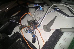
So I wanted to fly my Furibee with a normal transmitter.

Got a Robbe Starion at hand, ditched out the original electronics.

I have had several ideas for achieving my goal:

- Wire the Robbe's potentiometers to the Furibee's TX and call it a day.

- Reverese engineer the protocol and create a PCB with some random MCU (STM8 preferred) 

After some investigation the second option seemed to be a bit difficult so I have implemented the first option.

furibee_to_robbe_dip.sch

EAGLE Schematic

sch - 417.63 kB - 08/08/2017 at 19:46

Download

brd - 76.19 kB - 08/08/2017 at 19:46

Download

simulation.asc

LTSpice simulation

plain - 1.92 kB - 08/08/2017 at 19:46

Download

  • Notes about the "volt control" indicator

    Miklos Marton08/12/2017 at 11:58 0 comments

    Back in the eighties it was not usual to MCU-s with ADC-s to the RC transmitters which would have made the low voltage alarms easy. However the Robbe engineers used a small galvanometer to display the battery voltage:


    I have decided to repurpose this. I have connected it to a PSU and checked the voltage levels corresponding to the notable poisitions: full scale, red area start:
    - RED start: 1.3V
    - Full scale: 2.37V

  • Walking at the analog way

    Miklos Marton08/08/2017 at 19:27 0 comments

    So I wanted to marry the Robbe TX's good old Alps potentiometers to the Furibee's TX.

    The Furibee TX potentiometers were used at full range: their analog output goes from 0V to 3V3. While the Robbe potentiometers have different work range: when biasing them with 3V3 their range is ~1.2V -> 2.0V.

    So we need to came up with some analog circuit which is capable of amplifying the input signal (4,125) and offsetting it with a negative offset (-1.2V).

    This problem could be easily solved by an operational amplifier, but I have to note here that we need to use a rail-to-rail version since we need full range of output.

    First I went to the TME's search and looked for the cheapest Rail-to-rail OPA with 4 gates.

    It was the Microchip's MCP6004. It was available DIP package so it screamed for a quick and dirty solution.

    At first I have hooked up the schematic in LTSpice, for simulation purposes. Also hooked up the schematic in EAGLE to help the population of the prototype board.

View all 2 project logs

Enjoy this project?

Share

Discussions

Similar Projects

Does this project spark your interest?

Become a member to follow this project and never miss any updates