 MrWunderbar
Story
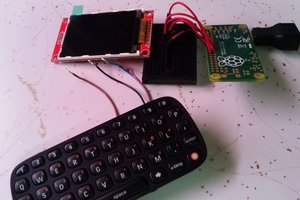
I started building a NAS from my old hard drives and got a Raspberry Pi as server. Then all the wires and everything was just laying around randomly and I thought that I should make a nice case for it.
First, I wanted to reuse old hifi equipment for that, but I couldn't find any cheap and broken device to salvage.
So I decided to get a custom made laser cut case and thought how I can add some nice elements that are not only decorative, but also having some extended functionality.
I like analog devices. Big nobs, needles, and there like, so I came up with the thought of adding some VU Meters to the case to have my system activity monitored.
I got some cheap ones from Taobao, but I think you can also find them on Banggoodor Aliexpress. Taobao is even cheaper than other online portals, but everything is in Chinese :)
Beginner Friendly Tutorial
If you go to the instructions section, you can find a full step-by-step guide that explains the whole process.
When I was finally done with the whole project, I thought that I should document it. And because it touches on so many different subjects (electronics, python, interfacing, GPIOs, PWM, etc), I thought I can make it as beginner friendly as possible.
Further Information
I got the basic know how on reusing old meters from the Post Apocalyptic Inventor, you can watch his video here:


 j0z0r pwn4tr0n
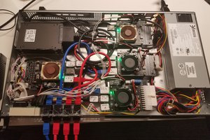
 tomtibbetts
 Dmitry
 Ash Johnson