Time to finish the cupboard at the back. This will house the electronics, so it requires some modifications. Once thing I want is electrical continuity throughout the enclosure, to act as an EMC shield and to add some safety. But riveting the sides together like I did with the other cupboard will already accomplish that. Besides that, I would also like it to be dust proof. One last requirement is that, for safety reasons, opening the enclosure must require some form of tool. So I need to add some typical enclosure locks. Here we go:
As implied by the teaser from the last log, I was planning to cut some holes in the sides. While we have a great assortment of machines where I work (at Umeå Institute of Design), this time I asked our neighbors for help. This is part of the result:
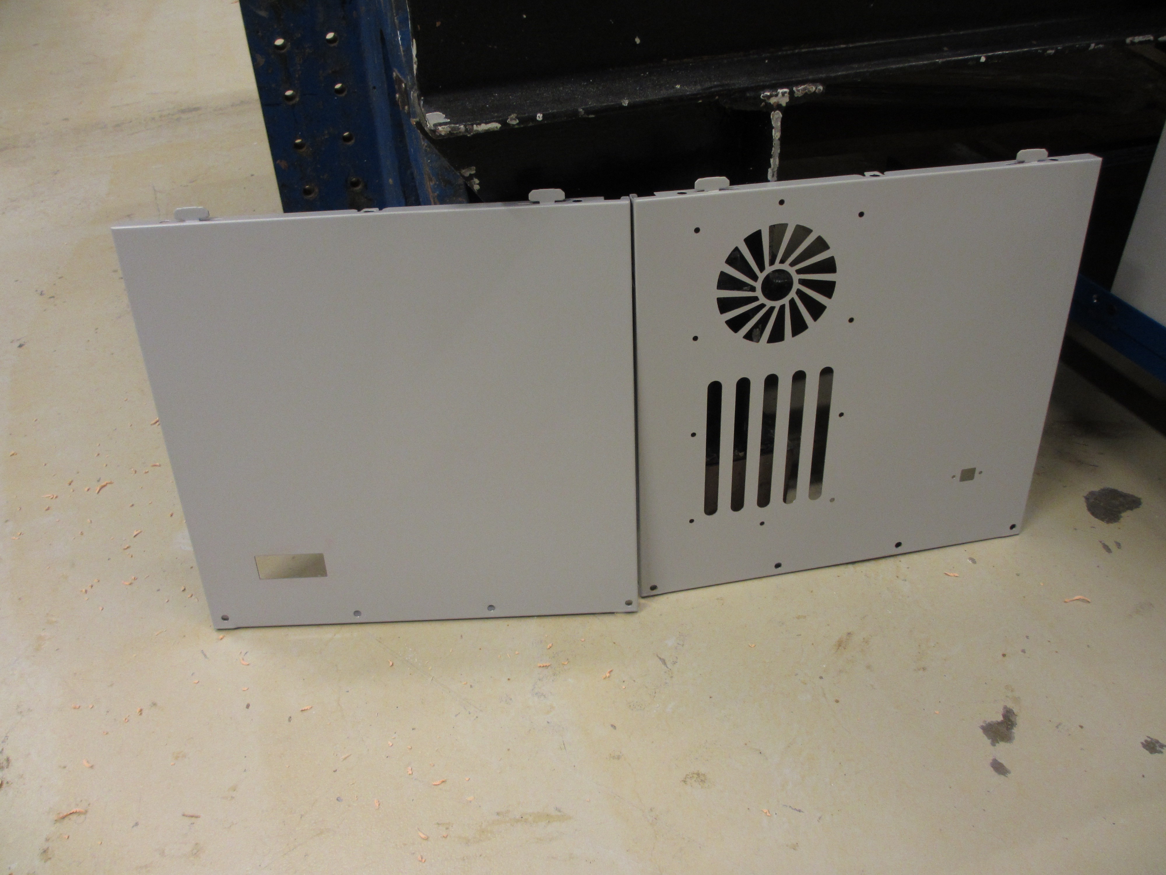
This was done with the water cutter at sliperiet fab lab (http://sliperiet.umu.se/en/happening-here/fablab/). Big thanks! The patterns were made using FreeCAD. I also made some paper mockups with the lasercutter before cutting it for real (as seen in the previous log).
With these cut, assembly can begin:
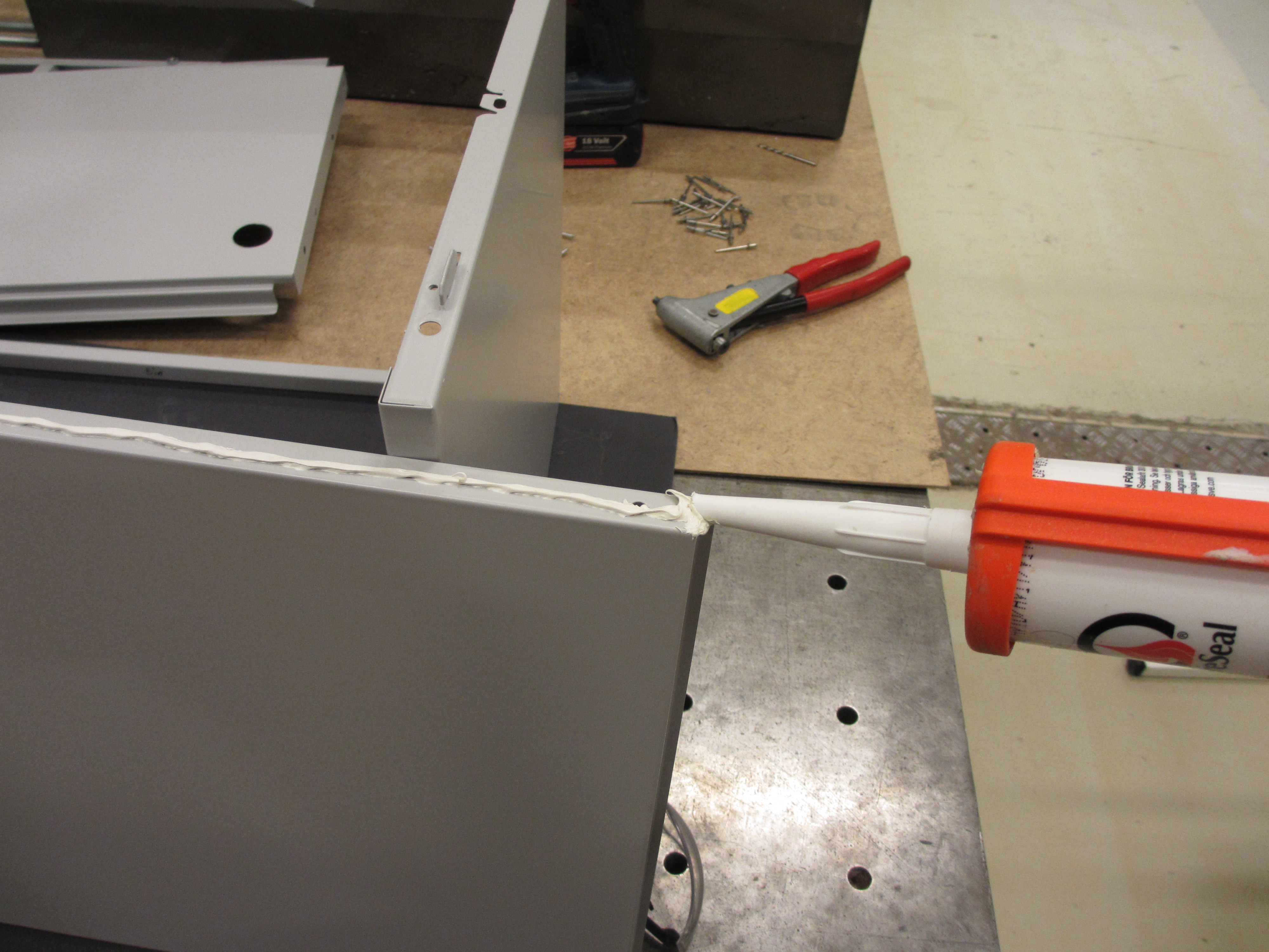
Silicone is applied as I go along, to keep it sealed. And very soon it was fully assembled. But in truth it was not that easy, it turns out the silicone was too old and never cured. So I had to wipe it of as much as I could and apply new sealant, which was especially complicated since I had already riveted everything together... I'll never make that mistake again, always check the expiry date of your silicone!
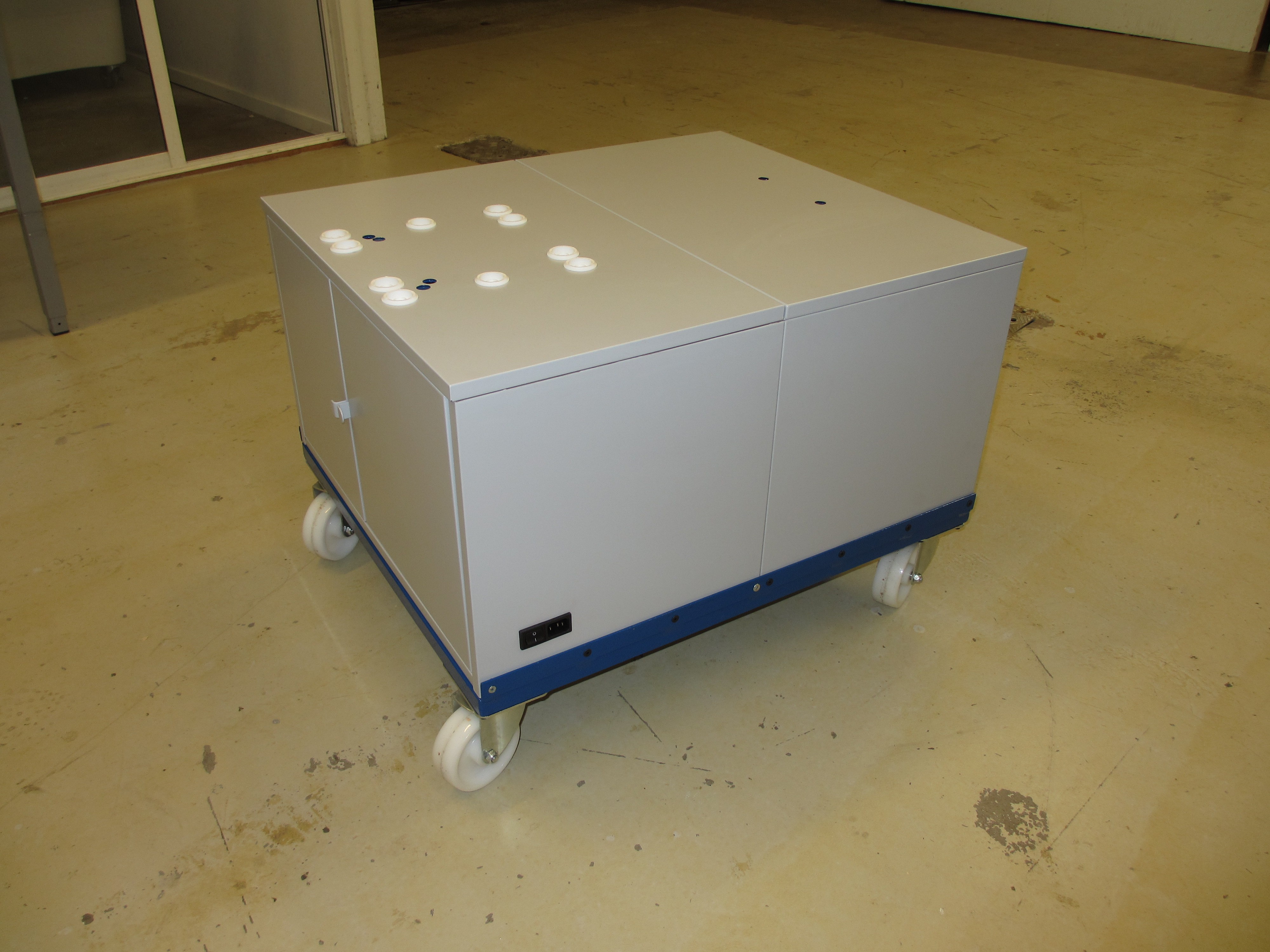
But here we are, so far so good. The connector and power switch is installed, as well as a USB port on the other side.
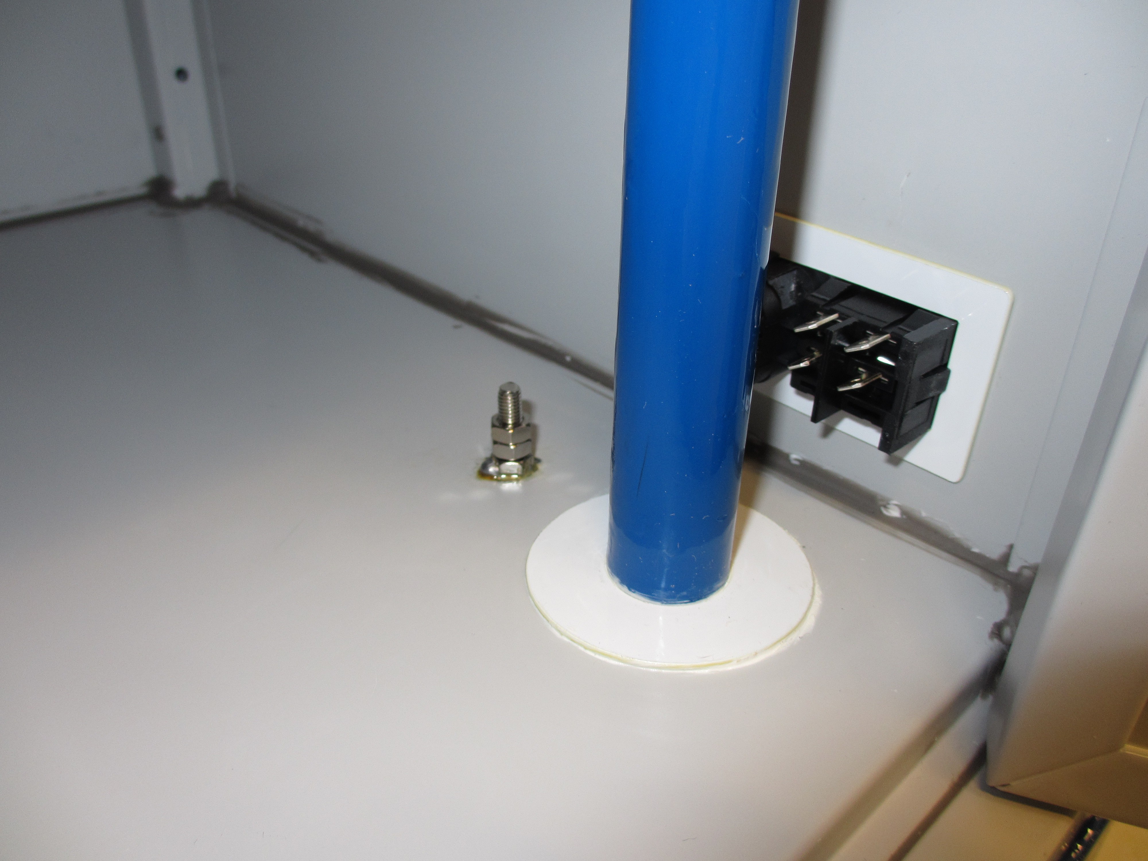
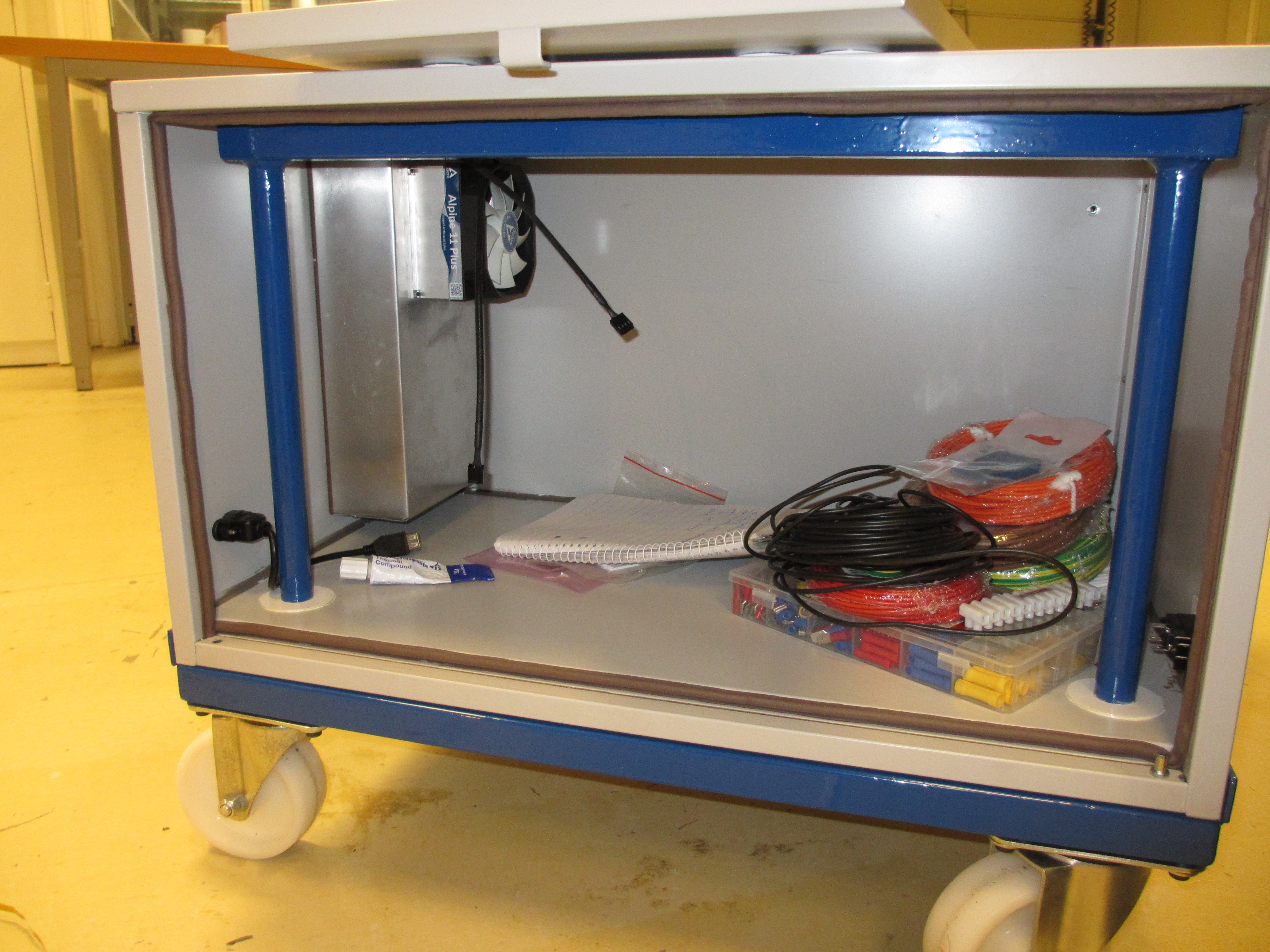
On the inside we have the same supporting frame as in the other cupboard, but with a laser cut plastic washer glue in place by silicone to keep it sealed. On the photo below you see this feature, but also the inside of the connector and switch (which has a similar laser cut washer for a tighter fit). You may also notice the screw sticking out of the floor. This is a nickel plated brass screw with brass nuts, and the bottom nut and the screw is soldered to the sheet metal. I sanded of the paint closest to the hole and used an ordinary soldering iron with tin. It worked very well, and it will serve as my safety earth connection.
Next up is the airtight heat exchanger. While I want the enclosure to be dust proof, it also needs cooling since it will house most of the power electronics. First up is buying two large heat sinks with fans, and I found the perfect product in the form of "arctic cooling alpine 11 plus".
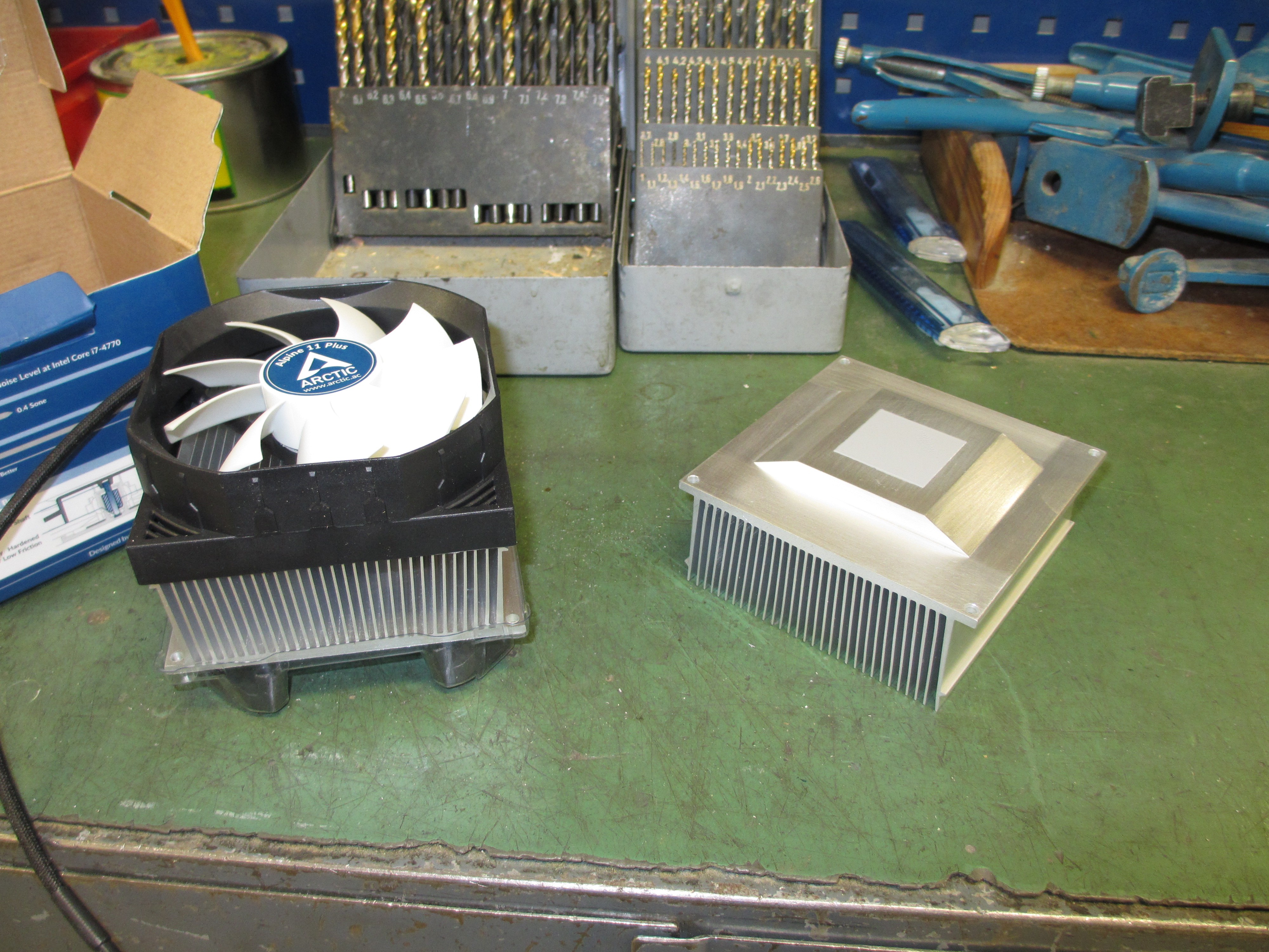
These are very cheap and have near perfect heat sinks. All I want to do is face them off a bit to get a larger area of contact, since they won't be used for a puny processor.
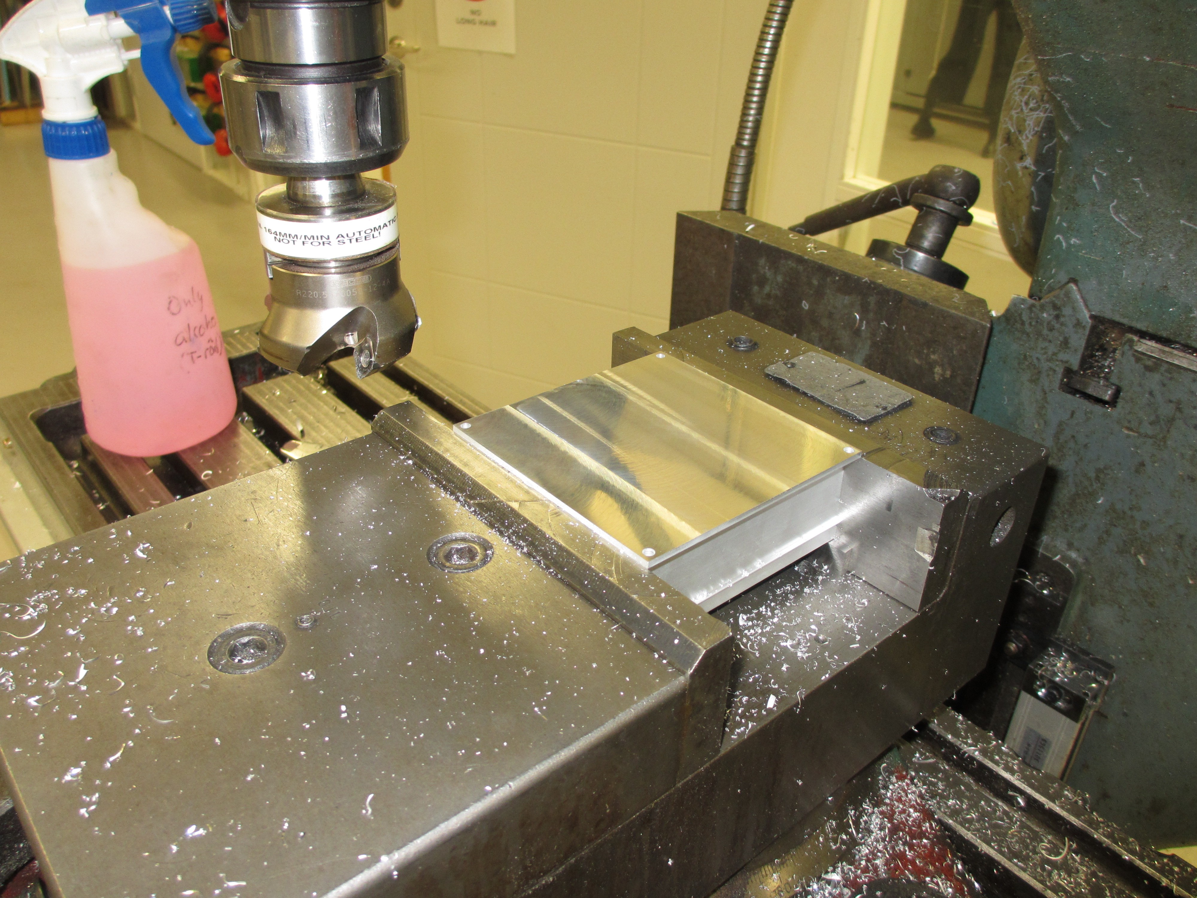
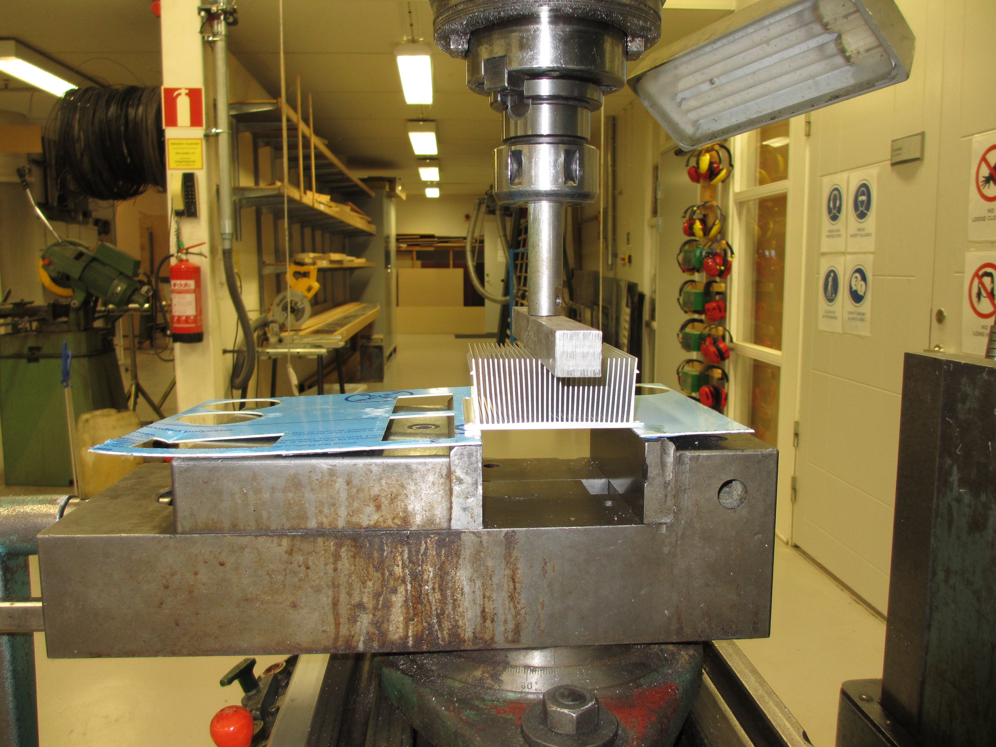
Mirror finish! I also tried placing it flat on the granite surface plate, and verified that it is now very flat and smooth. Reading up on heat sinks, flatness seems to be the most important factor, so this should be perfect. But I chose to question that. I decided that a convex surface should be best on such a large interface surface, in order to maintain pressure in the center. The reason why none of the sources on the Internet seems to agree with me is probably because most sources describe how to interface heats sinks with electronics. A convex heat sink would place stress on such components, but that is not relevant in my case. So here goes, after facing them I'm using the milling machine to bend them (while carefully protecting the surface finish):
 Next up is mounting the heatsinks to the aluminium box that I made (designed in Freecad and cut from 0,7mm aluminium in the water cutter at Sliperiet fab lab. Then folded together in our workshop). I started by rubbing all surfaces with fine steel wool and alcohol to smooth them out and remove oxides. Then cleaned it with paper and finally a lint-free rag.
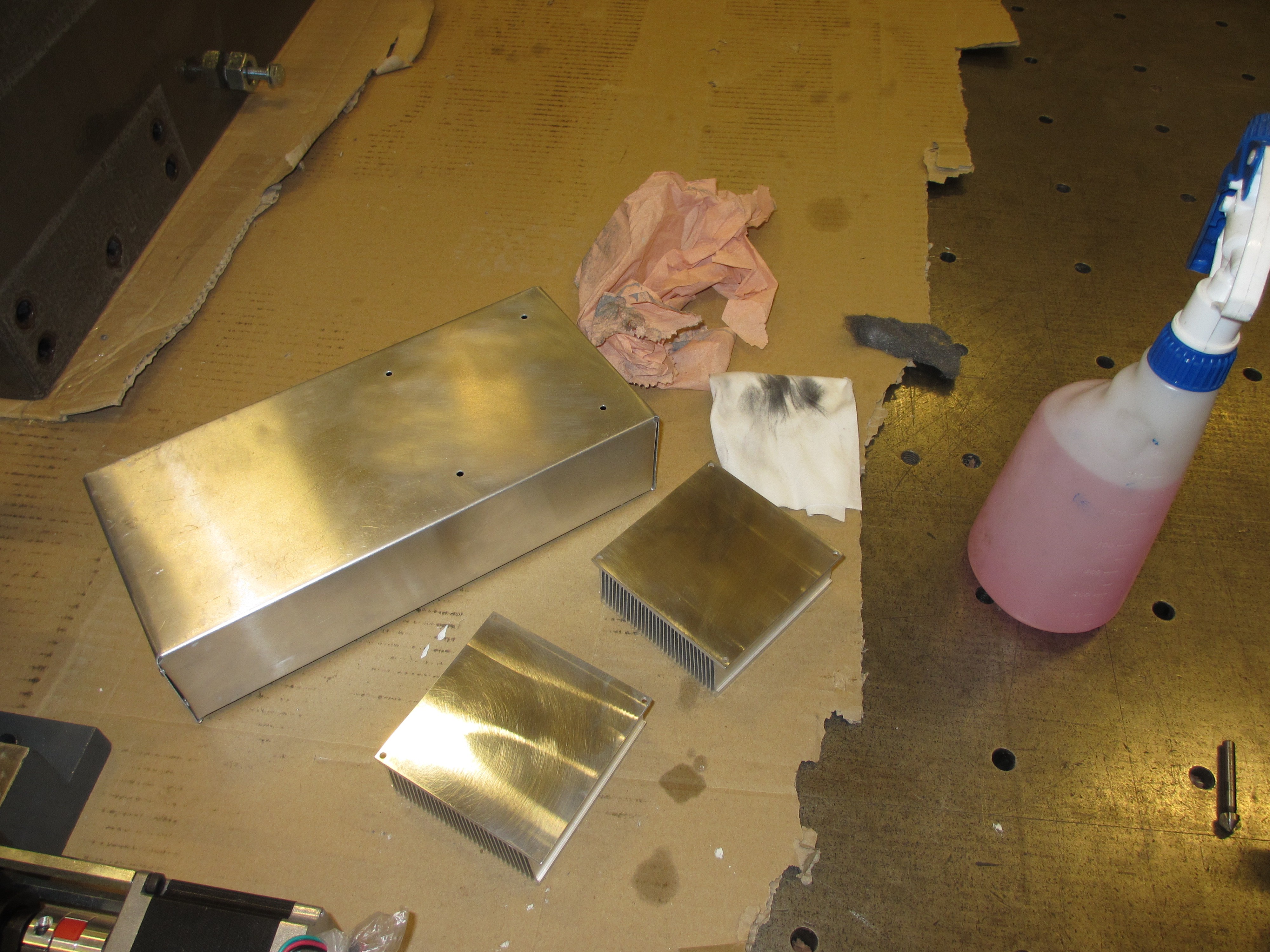
I started applying some thermal grease, only to find that it had separated badly...
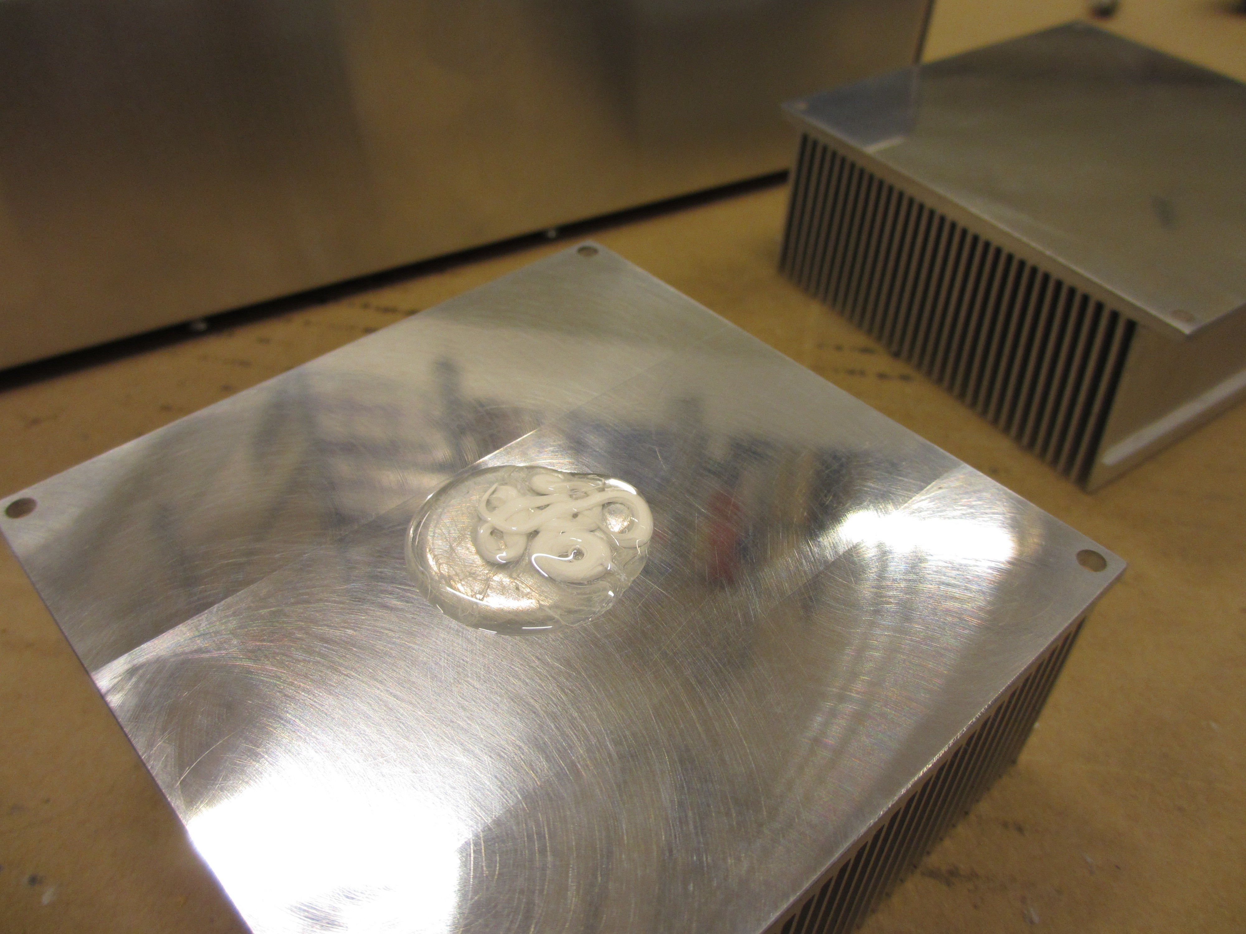
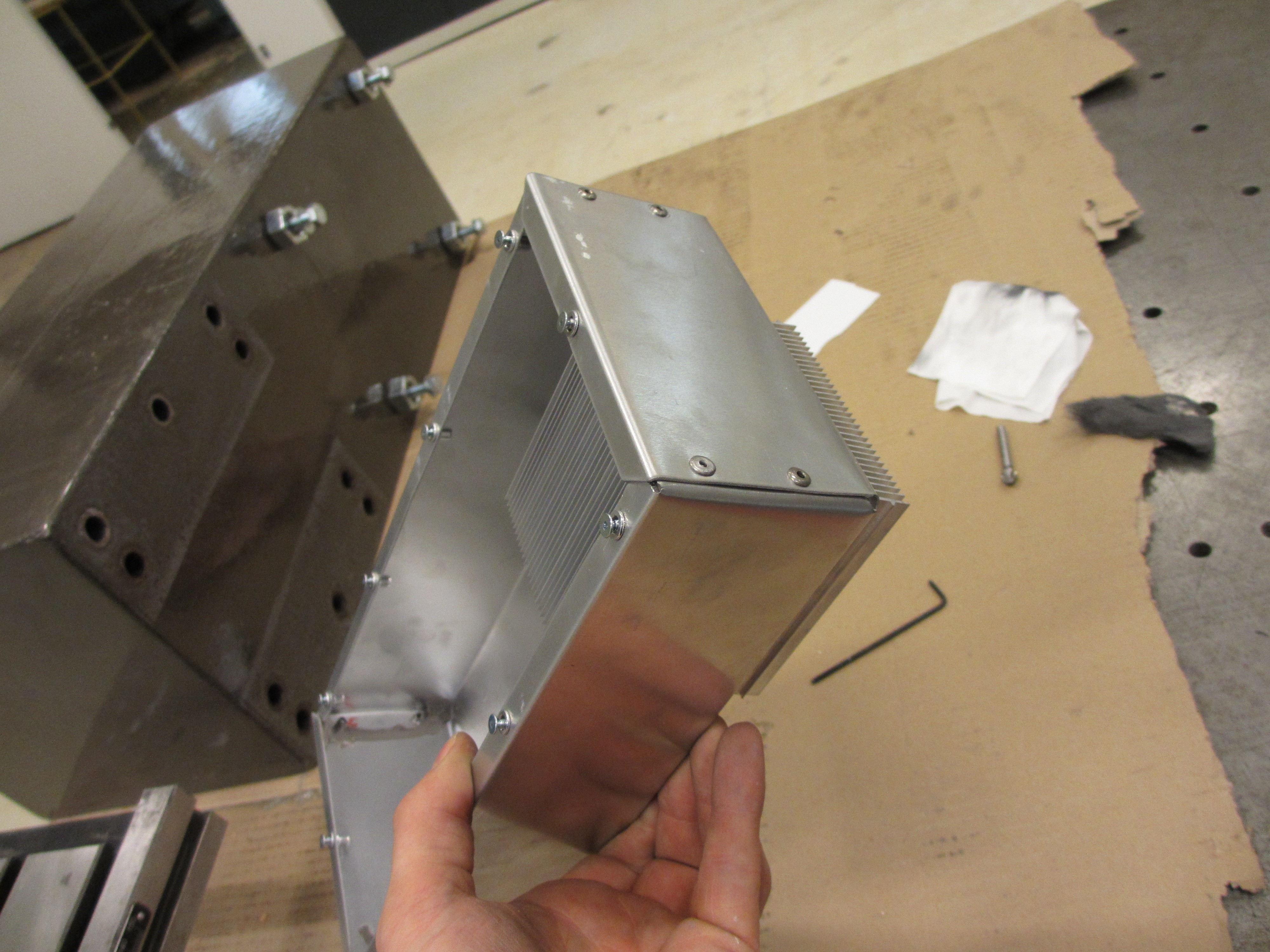
So i wiped it off and massaged the tube a bit, hoping it would mix again. this made it better, but not perfect. In the end I had to squeeze out a blob on the heatsink and mix on the spot it with my finger. Not the best way to apply thermal grease, but good enough I'm sure. here is a picture of only the box with the heat sinks, to give you a better understanding of how it's made:
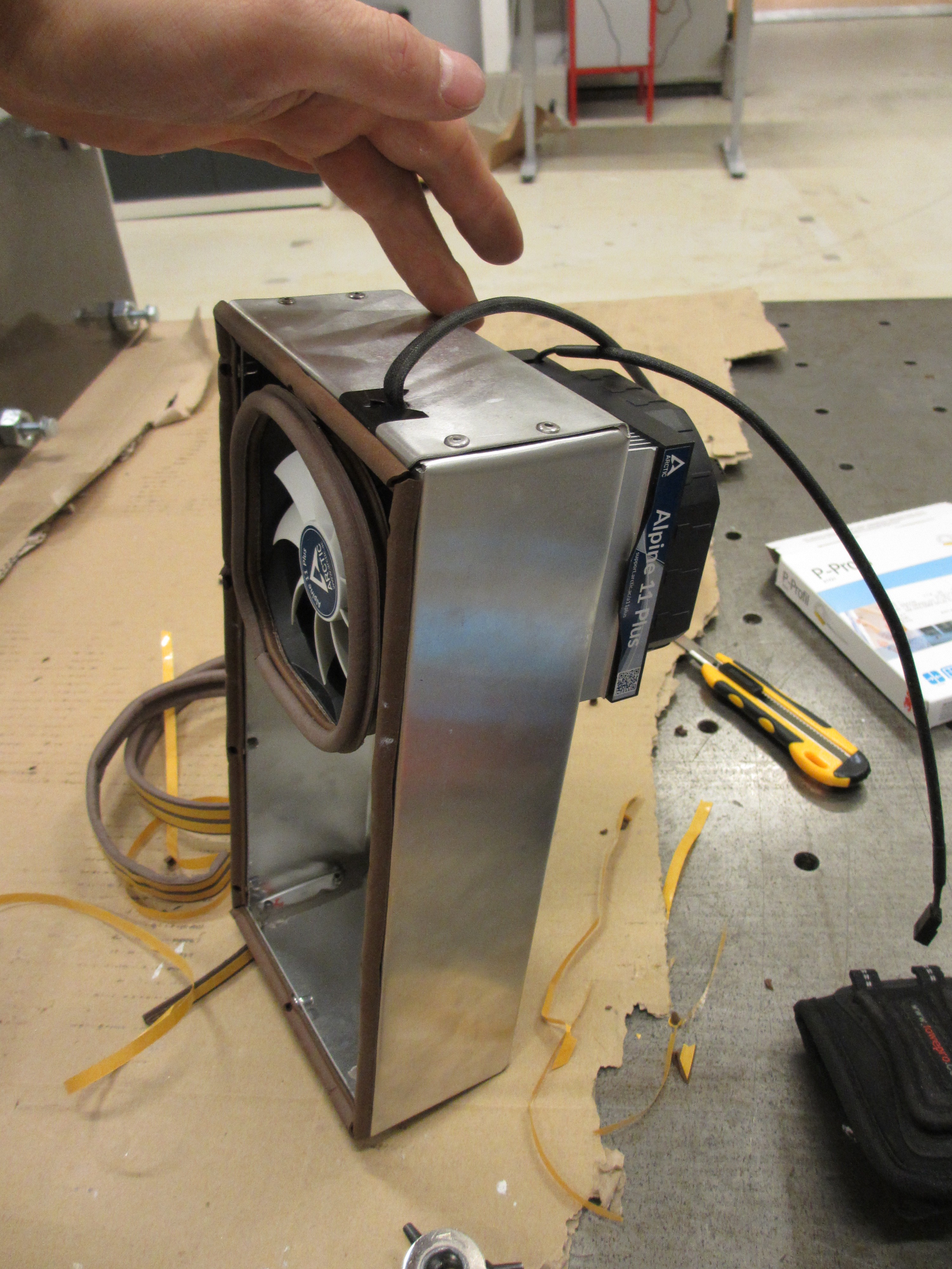
And here it is with seals and fans:
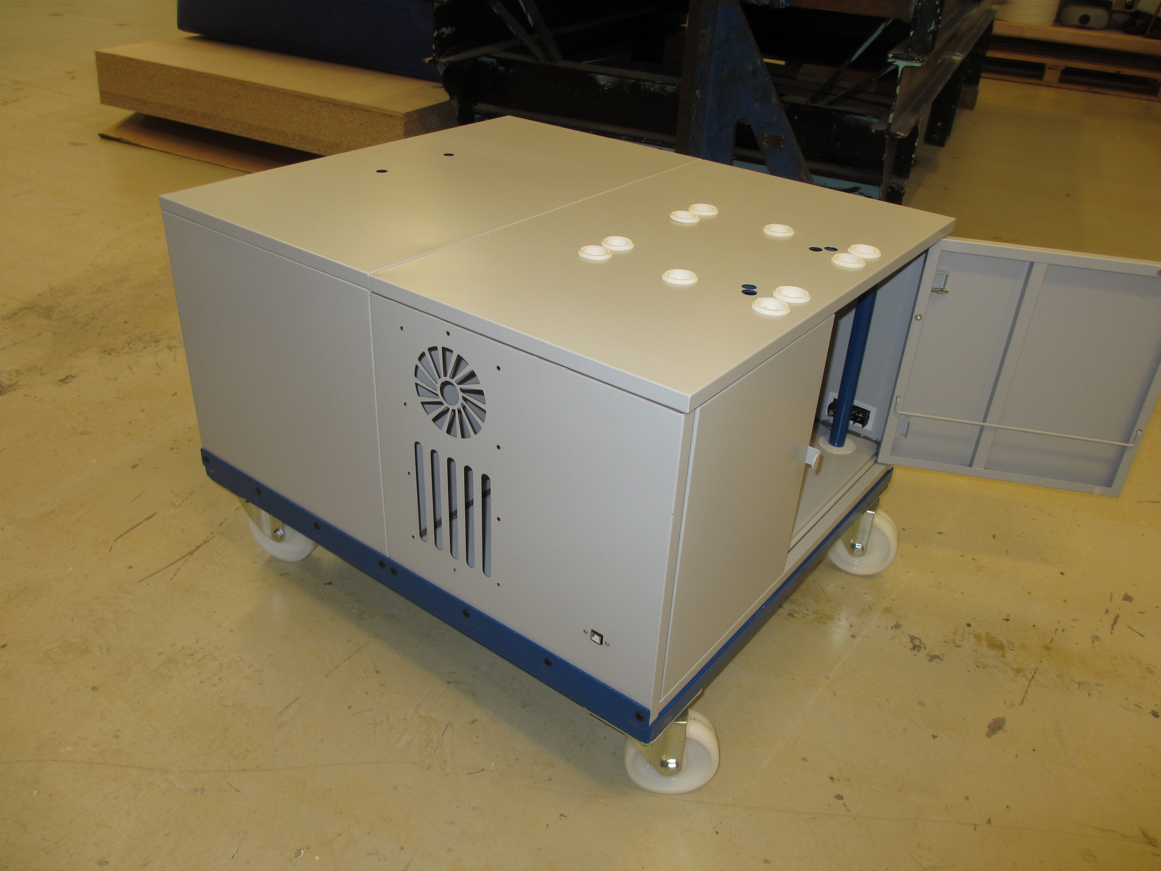
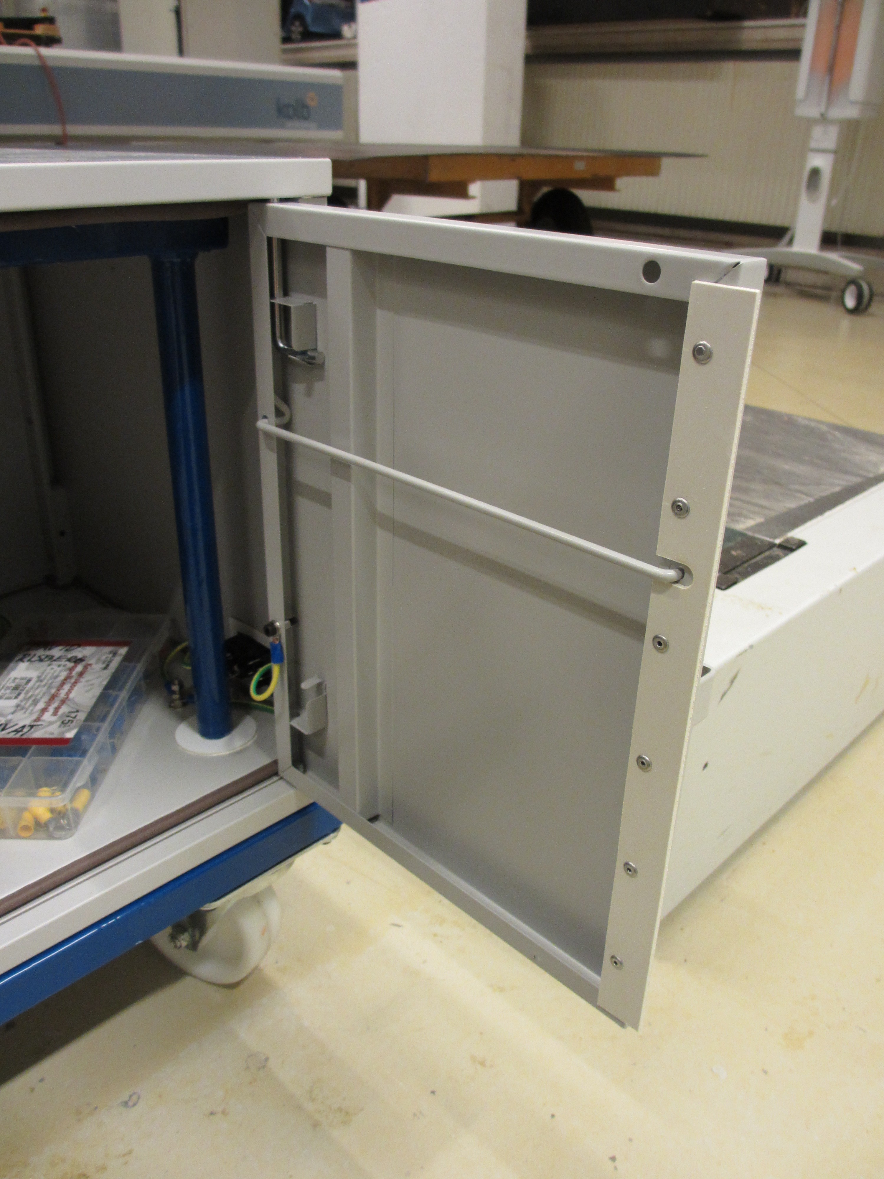
Next up is to screw it in place and add seals around the doors:
Last up is to place a strip between the doors, which will make it possible to lock both doors by only locking one of them. I made this detail from laser cut ABS and riveted it to the door. I think it will also seal well enough without adding foam seal, since the mating surface will be preloaded when the doors are closed. This picture also shows the safety ground cable connecting to the doors. All that's left now is adding the locks, but I haven't received them yet so that will happen later.
So there you have it! This whole carriage thing took waaay longer than I had planned, and totally ruined my schedule. In the end it had to be done, and I'm pleased with the result. so I'm not saying I regret it. But making the electronics enclosure dust proof, and therefor making this whole damned airtight heat-exchanger, that was totally overkill and a huge waste of time. I'm sure it will work, but I could have saved whole workdays by not doing it. I always end up over-engineering some stupid detail like this...
If you're building a CNC router to be used for wood: Please do copy my heat exchanger design for your enclosure. I'm sure you will love it. If you're building a CNC for metal, which does not produce the same type of dust, just make a bloody hole and stick a fan in it!
That's it for now, thanks for reading. The next several weeks will be quite busy at work, so don't expect another update before Christmas...
Discussions
Become a Hackaday.io Member
Create an account to leave a comment. Already have an account? Log In.