 The Current Source
At this point I'm digging through the junkbox looking for components that will work for this application and I'll eventually put this up as a YouTube video here. For now we're in the design phase. And before you say Arduino, RaspberryPi or BeagleBone, I just want it to plug in and work. No SD card power down issues, no fancy pants case, list of accessories, wireless, blah blah. Plug it in and get back to grilling.
Components I have on hand are:
1. Passives
2. Some op-amps, namely some old LM307's and LM324's
3. Handful of 1N4148's
4. Some NPN/PNP transistors (2N3904 & 2N3906)
5. Red LED for a comparator reference voltage
6. A fistful of magnet wire and a scorching antipathy for spoiled meat
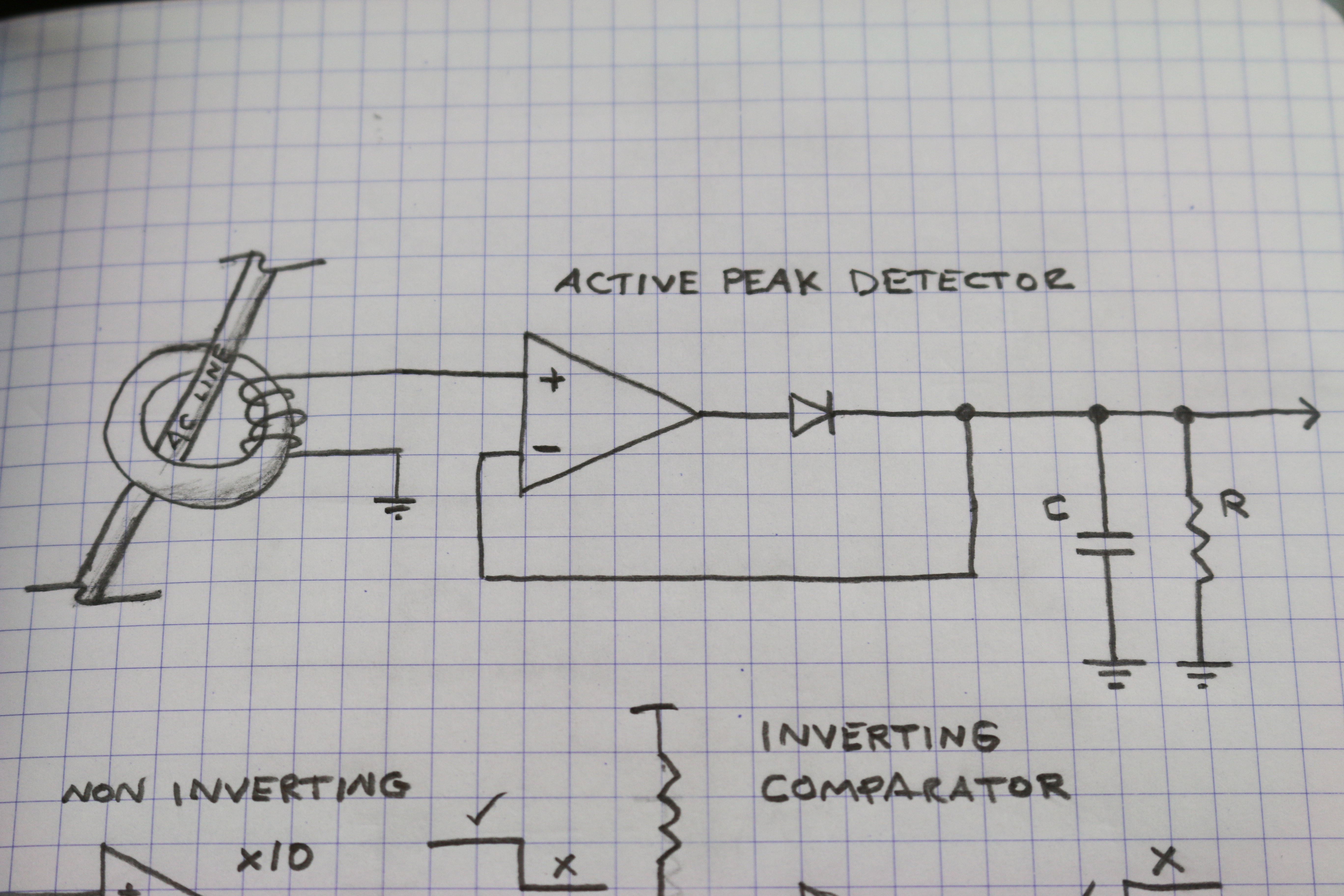
What I've come up with so far is an active peak detector, amplified to some gain to be determined, then through to a comparator which will enable/disable a 555 timer set to trigger an old "SONALERT" piezo buzzer at some annoying interval. Basic, nothing fancy and made from junk stuck deep in the carpet of my office. Perfect.
Active Peak Detector - In sensing the AC voltage (this is basically a barely effective transformer), just passing it through a small signal diode drops the ubiquitous 0.7 volts, eating up a lot of my coil winding efforts. So an active rectifier recovers a lot of what would be lost with just a small signal diode. That gets passed on to a capacitor (2.2uF) and a light, predictable load which turns this into an "Active Rectifier and Peak Detector" circuit - like peanut butter and jelly.
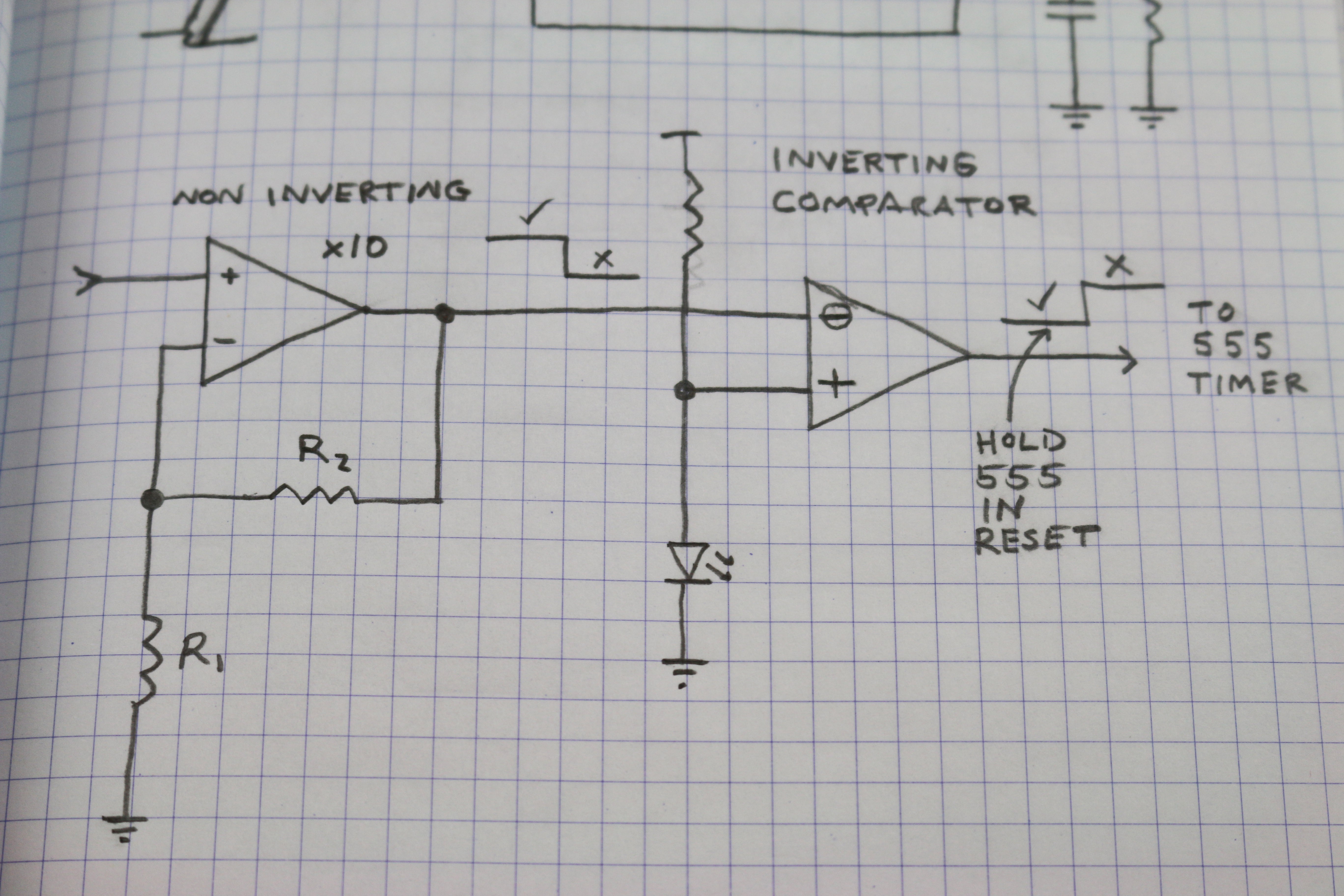
Preamp & Comparator - I'll need to bump up that output signal from the peak detector by some value to get above the LED voltage reference of the following comparator. I think that will be like 1.7v, though I haven't checked the particular batch of LEDs I have on hand. The comparator just does what it does. No hysteresis needed here because the peak detector is so slow, AC line transients are not an issue - or shouldn't be :)
I'm still thinking about the inverting comparator and wonder being a single supply rail if it'll slam down close enough to the negative rail for the 555 reset. It may be that I use an inverting gain stage and a regular non-inverting comparator instead. That makes sense right? Hmmm.
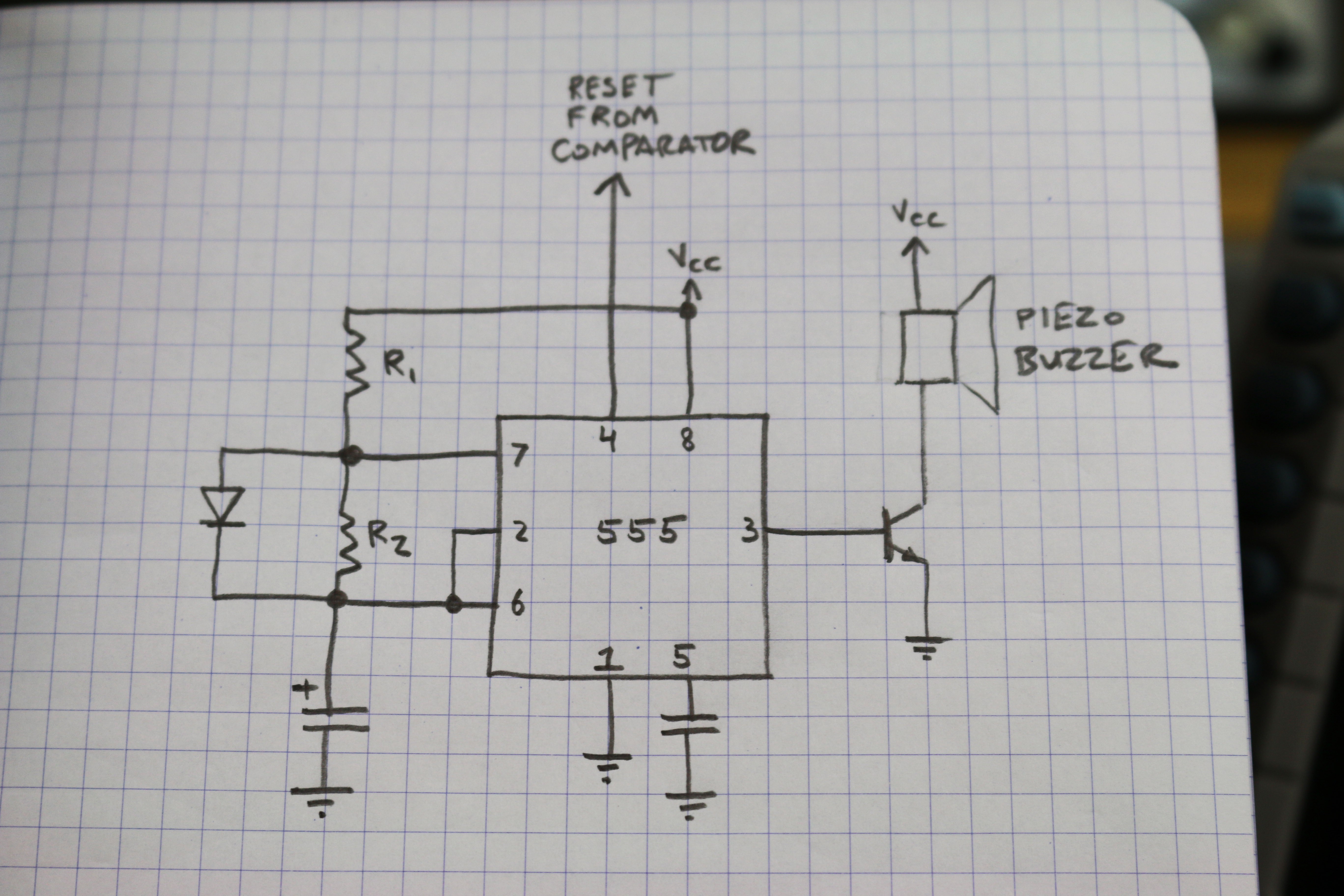
555 Astable Multivibrator - Who doesn't love an astable multivibrator? Reset line is controlled by the previous comparator. The timing components R1, R2 & that electrolytic I forgot to label control the timing of the buzzer. I'll probably make the period something like 1.5sec or in that neighborhood. What's the diode? A little trick for getting 50% duty cycle. Without it, a 555 can never be less than 50%. Since a 555 charge path is through [R1, R2 and the electrolytic] and the discharge path is only through [R2 and electrolytic], guess what? We can't have a 50% duty cycle - the charge and discharge paths are different. But, if we make R1 and R2 equal and stick a diode across R2, the charging path becomes [R1 & electrolytic] while the discharge path becomes [R2 & electrolytic]. Bam! 50%
Discussions
Become a Hackaday.io Member
Create an account to leave a comment. Already have an account? Log In.