 Yann Guidon / YGDES
This log continues 43. Data retention times of hysteretic relay latches, I'm digging more into the practical details now.
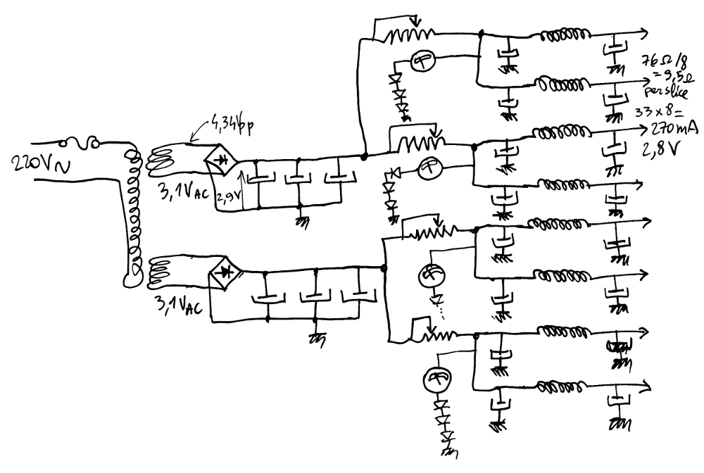
First, the fuse (you don't want this to happen) then the transformer: the TSL40/001 from INDEL. The high voltage output is ignored, I only use the 3.15V outputs. There are 2 outputs and each can supply 3A but the register set needs 2.1A (total) so each half will provide only 1A. The extra power can be used for other parts of the circuit.
I have not found suitable Selenium rectifiers for the bridge rectifier. The peak current could be in the 3 or 4A range. I just spotted some Germanium power diodes, we'll have to wait for their delivery to test them. At high current, their drop can become "significant" so I cross my fingers : the output should be around 3V or 2.9V. If we consider the diode drop of silicon diodes, this is achievable, and the Schottky diodes can always be used as a last eventuality.
A few big capacitors filter the bridge's output then the rail is split into two : each half-rail has a small rheostat to "drop" some fractions of volt, and the result is measured with a small solenoid indicator. I'll calibrate the measurements so each branch has the correct voltage and reading. Some diodes drop the voltage so only 60µA flows through the solenoids at the right working point.
Finally this sub-sub-branch is split again and powers 2 "slices", each with their own capacitor-inductor-capacitor filter for the extra smoothing.
So far the only thing I don't have right now is the diode bridges, but I just ordered these parts.
Germanium has a naughty tendency to drift with temperature. The bad way. The behaviour will change with the load and I don't have all the register boards to draw the expected current. I can however simulate one slice (of 8 relays) with 4 resistors in parallel: I have a bunch of YAGEO 39 Ohms 5% 1/2W that will do the trick, the whole set would be emulated by 32 resistors (with each resistor used at half of max. power rating). It's still a progress...
I didn't check enough but... The low voltage secondary is made of 2 windings that are joined in series. I hacked it to make them independent again. Notice the small writings : the 3.15V windings have one pin in common...

The construction quality is good so it was not hard to separate the 2 windings. I just wish I noticed it earlier !
The resistance of the 3A circuits is very low, I can't measure it with my multimeter. It's going to be very powerful...
Discussions
Become a Hackaday.io Member
Create an account to leave a comment. Already have an account? Log In.