A limited number of the extra badges are available on Tindie.
General description and firmware functionality
Other sections :
- Firmware hacking and adding new applications
- Bootloader
- Hardware Description
- Hardware hacking
- Badge hacks list
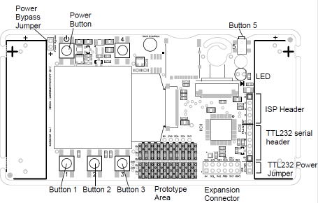
Button numbers and header locations
Power control : Pressing the power button turns the badge on. Pressing and holding a couple of seconds turns off.
Holding the power button at startup will display all the power-up button functions.
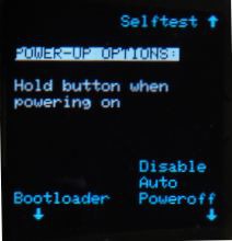
Auto powerdown : the device will power down if no button is pressed, or no significant accelerometer movement is detected for 10 minutes.
Holding button 3 on powerup disables the powerdown timeout. Holding button 4 on powerup performs a hardware selftest (see later).
Splashscreen : At startup, if SPLASH.AVI exists on the card, it will be played once. Embedded framerate is ignored -it plays at maximum rate. This should be a short file to avoid excessive startup delays. If SPLASH.AVI does not exist, it looks for SPLASH.BMP and if present, displays it for a second or so.
At startup, a menu is displayed allowing selection of various applications.
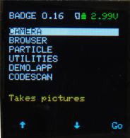
The menu screen also shows the battery voltage ( coloured green, yellow or red to show status), and a card symbol to indicate when a MicroSD card is inserted and successfully mounted.
MicroSD card support : FAT16 or FAT32, no long filename support.
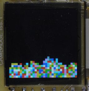
Camera application
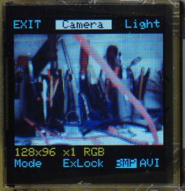
Displays live camera image.
Button 1 selects the recording format (resolution, zoom, colour/mono).
Button 2 locks the camera's auto-exposure value
Button 3 toggles between still ( BMP) and video (AVI) recording.
Button 4 Toggles the illuminator LED
Button 5 takes an image, or starts AVI recording, and stopped with any button.
Images are stored in the CAMERA folder, Videos are stored in the CAMVIDEO folder. (folders will be created if not present) The filename will be the first unused name in the form "CAMnnnn.BMP" or "CAMnnnn.AVI", where nnnn is a number. If you delete files, new captures will be given the number of the deleted file(s) until the "gap" closes.
File formats :
- Saving BMP : resolution 128x96, 8 bit mono or 24 bit colour ( expanded from 565),
- Saving AVI : resolution 128x96, 8 bit monochrome or 16 bit RGB565
- Higher resolutions, using SPI SRAM to expand memory is currently under investigation.
Video framerates : 128x96 Colour 3-10fps, mono 5-16fps. Zoomed modes will have slightly lower framerates. Rate is extremely dependent on teh individual SD card. Frame rate in AVI file will be set to the avarage capture rate measured over the whole recording, so should play back at similar speed to recording, but may have occasional "lumps" due to SD card timings.
Initial testing of SD cards shows that smaller cards (256MB and below) can be substantially faster, with write speeds up to 330KBytes/sec, vs. 80-150Kbytes/sec for larger (512MB+) cards. The utilities application has a speed tester to allow quick selection of cards for maximum speed.
Note that all camera modes crop an image from the whole sensor area, but the camera's auto-level control acts over the whole sensor, therefore bright lights outside the field of view may cause the exposure to be significantly non-optimal. This effect will be more noticeable in the zoomed modes, where a smaller part of the sensor is visible.
File compatibility with software packages.
** PLEASE ** let us know in comments about non-Windows software options.
Sample files are included in the files section.
VLC (Windows and Android) : Plays monochrome AVIs but not RGB565 colour
Windows meda player : Plays RGB565 colour, but not monochrome
Virtualdub (windows) : Plays all formats, creates all formats.
Final media player (Windows) : plays all formats
The following are all reported by others to be compatible with both formats :
mpv, ffmpeg (e.g. ffmpeg -i avi_rgb565.AVI out.mp4 ) , Handbrake
Android mx player, Blender, Kodi, kldenlive, kino , ffplay
See this page for info on using ffmpeg to create videos to play on the badge
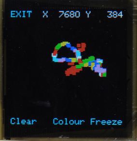
Particle application
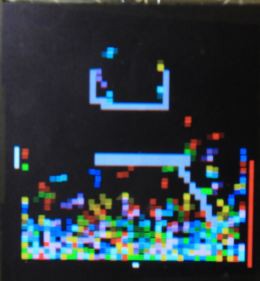
Gravity particle toy using crude hack physics simulation.
Press button 1 to shake up a little, button 2 to change number of particles, button 3 to change particle size.
If left still for a while, the particles will get bored and start "fizzing" an an increasing rate. The red bar on the right indicates current fizzing level - increases over time when not moved, moving reduces it.
Button 4 enters edit mode, which allows obstacles to be added & removed to make things more interesting
In edit mode, the particles freeze, and a flashing cursor, controlled by tilting, shows the current edit position.
Button 1 selects the pen size ( 1 or 4 pixels), button 2 clears pixels at the cursor posiiton, button 3 sets pixels. Hold button 3 and tilt to draw lines. The power button clears all obstacles. If an obstacle is drawn over a particle, that particle will be moved in a random direction until it finds a free pixel position.
Button 4 exits edit mode.
Changing particle size clears obstacles, but changing numbers retains the obstacle data.
Browser application
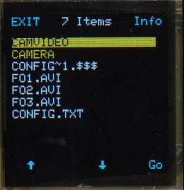
Allows browsing files on SD card. Displays BMP and AVI files, shows file info ( date, resolution for BMP/AVI, fps and number of frames for AVI).
Info and BMP view functions also allows file deletion via the preview and info functions. For deletion, button 2 must be held for approx 0.5 secs to avoid accidents.
When a folder is selected, the "Info" (button 4) function becomes "Show", which plays a slideshow of BMP files in that folder. Any suitable file (<=128x128) will be displayed, and any unsuitable ones skipped. During slideshow,, buttons 1 & 2 select the speed, button 3 manually advances, button 4 toggles display of the filename.
File formats understood :
- Loading BMP : up to 128x128 pixels, 8 or 24bpp
- Loading AVI : must be uncompressed with no audio, up to 128x128 pixels, 8 bit mono, 16 bit RGB565, 24 bit 888.
Framerate specified will be attempted, but may be limited by bandwidth ( e.g. a 1fps file will display at 1fps, 60fps will be slower).
RGB565 will play back faster than RGB888 - as the display is RGB888 there is no quality advantage to 888, but it is a more widely supported format so may be easier to generate.
If image height <=96 pixels, current frame and time will be displayed at top of screen. File may be paused and deleted. (Delete requires a long keypress). See this page for info on applications for creating and converting suitable AVI files
Utilities application
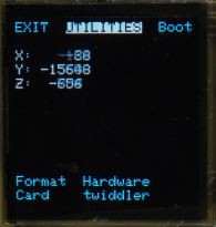
Displays accelerometer values. Allows access to bootloader and card formatting ( Note formatting may not work on cards >2GB).
Card write-speed test allows evaluation of SD cards - There appear to be significant speed issues writing small blocks in SPI mode on larger (>256MB) cards. This utility allows quick screening of cards to find ones that will give better video record rates. Anything that reports over 250kB/s is a good card
Button 2 runs a simple hardware exerciser to set and read pins on the expansion header :
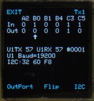
Current state of all the header I/O pins is shown on on the "In" line ( updates every 20mS)
Current state of the output latch bits is shown on the "Out" line. Whether or not these are reflected on the "In" pins depends on whether the pin is set as an input or output, or if the pin is mapped to a peripheral. By default RB0 is UART2 TXD, RB1 is UART2 RXD.
Pressing Button 2 toggles the state of the output bit above the arrow. Button 1 selects the bit to be toggled.
If bytes are received on UART1, the last byte received, and the receive byte count are displayed.
Pressing "Tx1" sends a byte on UART1 ( starts at 0x55 then increments on each press). UART1 pins are set as I/O at startup, but switched to UART functions the first time a byte is sent on UART1, so pressing this enables the UART for Tx and Rx. Linking pins 8 and 10 on the header will show the transmitted bytes being echoed back,
Button 3 scans all addersses on the I2C bus and shows the address of each device found.
Demo application
Simple accelerometer doodler for use as a template for user applications
CodeScan application
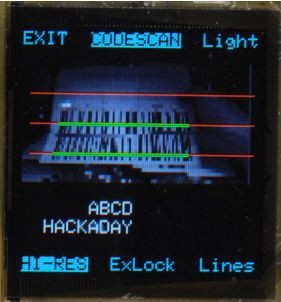
Experimental reader for code-128 barcodes. Due to the camera's focal distance, these need to be printed really BIG - about 6 inches wide for a 4-character code. The slicing algorithm is probably suboptmal so it is quite sensitive to lighting conditions, but works very well with codes on a monitor screen due to the high contrast.
The reader scans continuously and displays any successfully read code onscreen. Up to 4 read lines can be selected, to read multiple codes simultaneously. A hi-res mode allows higher capture resolution for longer codes by running the camera in SXGA mode, at a slower framerate.
To make a code, use this online code creator Select Code 128, scale around 6-8 x 2 Note that codes with more than one consecutive numeric will not decode correctly as the reader doesn't currently implement the optimisation for numerics
Oscilloscope
 SImple 2-channel oscilloscope. Inputs via RB0 & RB1 pins on ISP header, TTL232 header and expansion header.
NOTE THERE IS NO INPUT PROTECTION! Inputs outside the range 0 to +2.8V may damage the PIC.
Triggers on selectable rising or falling edge on Ch1 only, with settable level. Input range is 0..+2.8V, and display can scale the 0-1023 count input range by up to x8 for 100mV/division.
Button 1 selects the thing that is adjusted using buttons 2 & 3. Cycles through : Y1 volts/div, Y1 offset ( position), Y2 volts/div, Y2 offset, Timebase, Trigger level. In the latter mode, button 5 selects the trigger edge.
Y1 and Y2 zero is indicated by a dotted line in the colour of the respective channel. Trigger level is indicated by a white dotted line, and as a voltage at the top of the screen.
Button 4 freezes the current waveforms.
A trigger timeout operates in the absence of a valid trigger signal.
Hardware selftest
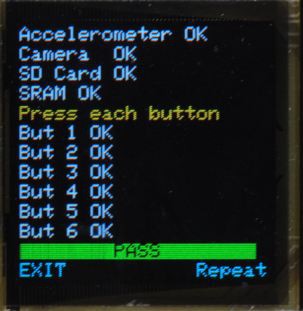
By holding button 4 at powerup, a hardware selftest is performed. This fills the screen sequentially with red, green and blue to check for bad pixels. The I2C bus is then checked, and I2C comms to the accelerometer and camera are tested. The camera data bus is checked for incoming data, and if any lines appear to be open these will be listed ( with the FFC and PIC pin numbers).
If an SD card is inserted, it will attempt to mount it to check the SD card hardware. The SRAM is tested, and the battery voltage is checked for a sensible range (2.5-3.5v).
The user is prompted to press each button, and when all have been seen, the test shows a "Pass" indication. Any failure will stop at the point it failed.