 Cloud4RPi
This article was sent to us by one of our early adopters who develops a DIY hydroponics system at home and uses our service for it. We are happy to publish it here.
Recently I got the UniPi board and decided to test the Cloud4RPi service on a real-world task.
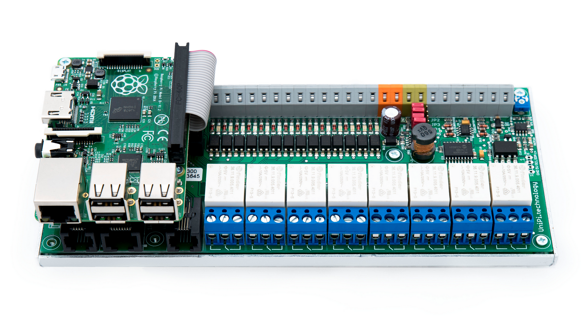
UniPi is a Raspberry Pi single-board PC combined with the controls and sensors board connected via I2C. The board has the following hardware:
- Relays (250V/5A) x8
- Analog Output (0–10V) x1
- Analog Inputs (0–10V) x2
- Digital Inputs (5–24V) x14
- 1 Wire bus
- I2C bus
- UART port
t’s more than sufficient for control automation and data collection. The desktop-class operating system on Raspberry Pi is also a big advantage.
The official control software is Node-RED, which allows you to create algorithms for IoT devices in graphical mode. The Node-RED setup is described well in this manual, I had no difficulties with it.
Cloud4RPi is a control panel that enables you to control all your devices via the Internet and log history. The Cloud4RPi-enabled device can communicate with the Cloud in two different ways: via the MQTT message queue and via the HTTP Web-API. In Node-RED, we can implement both ways, but MQTT seems to be the better option.
Node-RED has a set of tools for this: mqtt-broker to setup broker connection, and a node to send and receive messages. Cloud4RPi has two types of messages:
- Messages that the device sends to the cloud. Used for initial configuration, status reports and sensor data.
- Messages sent from Cloud4RPi to the device. Used to deliver commands sent from the Control Panel.
First thing you need to do is to configure the device, i.e., send the variables list to the devices/{token}/config MQTT topic. The message should be in JSON format and look as follows:
{
  "ts": /* Date & Time in ISO 8601 format */,
  "payload": [
    {"name": "Boolean Variable", "type": "bool" },
    {"name": "Numerical Variable", "type": "numeric" },
    {"name": "String Variable", "type": "string" }
  ]
}
Messages with data are sent to the devices/{token}/data channel in the following format:
{
  "ts": /* Date & Time in ISO 8601 format */,
  payload: {
    "Variable Name": "Variable Value",
    "One more variable": 42,
    /* etc... */
    "Yet another variable": false
  }
}
You can also send the diagnostic data that is not logged to the devices/{token}/diagnostics channel:
{
  "ts": /* Date & Time in ISO 8601 format */,
  payload: {
      "Diagnostic Variable": "Variable Value",
      "Another Diagnostic Variable": 12
  }
}
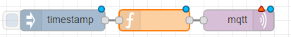
To configure the MQTT connection in Node-RED, add the flow node that will subscribe to topics and send messages to them:

Double click it to open the configuration menu:

In the Server field, you can choose the existing server or add a new one:
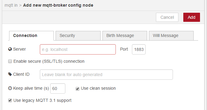
The Cloud4RPi Connection settings are the following:
- Server:
<a target="_blank" rel="noopener noreferrer" href="http://mq.cloud4rpi.io">mq.cloud4rpi.io</a> - Port:
1883 - Client ID: (Your Device Token)
- Use legacy MQTT 3.1 support: Unchecked
You can find more info in the documentation and Python client library.
After the server creation, it will become available for selection in any subscription or broadcasting node. You can create as many nodes as you need to make the scheme more readable.
In the node configuration, you should also specify the channel to communicate with. The channel list is presented below:
devices/{token}/config        - variables configuration
devices/{token}/data        - sending variable values
devices/{token}/diagnostics    - sending diagnostic data
devices/{token}/commands    - receiving commands from UI (subscribe to this one)
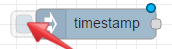
The first thing we need to do is to send the variables configuration to Cloud4RPi. I need to do it on device startup, for which I added the inject node

and checked the following checkbox in its settings:
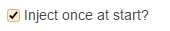
Now it will trigger at the system startup. Additionally, you can trigger it by clicking here:
This node should trigger the variables configuration sending devices/{token}/config channel, but the data package should be initially shaped. Let’s use the function node for this:

It’s possible to write any JavaScript code here, so let’s just return the configuration in the appropriate format:
var message = {
    ts: new Date().toISOString(),
    payload: [
        {"name": "Bool Variable", "type": "bool"},
        {"name": "Number Variable", "type": "number"},
        {"name": "String Variable", "type": "string"}
    ]
};
return {payload: message};
Note that the data package for the mqtt node should be contained in the payload element of the associative array sent by the activating node.
Now let’s connect three nodes together and trigger this chain:
After that, the config message should be sent and we will see the following on the device page.
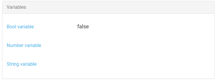
The next step is configuring the real hardware-specific variables and sending their values.
The UniPi API communications are described here. We are interested in HTTP and Websocket: HTTP to request the device state, and websocket for receiving information about events instantly.
I’m sending the variable values in the following cases:
- On system startup to actualize the control panel
- On variable change sending only the changed variable
On system startup, it’s better to send variables just like the system configuration. We can do it from the same node with a delay, to let Cloud4RPi receive the config.
This can be done with the delay node:

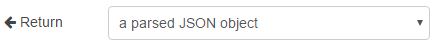
To get all UniPi variable values, make an HTTP request to the <a href="http://{unipi/" class="markup--anchor markup--p-anchor" rel="nofollow noopener" target="_blank">http://{UniPi</a>IP address}/rest/all address using the http request node:

In its settings, set the following option that will make a JSON object from the HTTP response:
After receiving all values we’ll use the function node to assemble the JSON message for Cloud4RPi.
var getMsgValue = function(device, circuit){
  return msg.payload.filter(function(val){
      if(!val.dev){
          return false;
      }
      return val.dev === device && val.circuit === circuit;
  })[0].value;
};
var message = {
    ts: new Date().toISOString(),
    payload: {
        "Relay 1": getMsgValue("relay", "1") === 1,
        "Relay 2": getMsgValue("relay", "2") === 1,
        "Relay 3": getMsgValue("relay", "3") === 1,
        "Relay 4": getMsgValue("relay", "4") === 1,
        "Relay 5": getMsgValue("relay", "5") === 1,
        "Relay 6": getMsgValue("relay", "6") === 1,
        "Relay 7": getMsgValue("relay", "7") === 1,
        "Relay 8": getMsgValue("relay", "8") === 1
    }
};
return {payload: {message}};
You should use the following config:
var message = {
    ts: new Date().toISOString(),
    payload: [
      {"name": "Relay 1", "type": "bool"},
      {"name": "Relay 2", "type": "bool"},
      {"name": "Relay 3", "type": "bool"},
      {"name": "Relay 4", "type": "bool"},
      {"name": "Relay 5", "type": "bool"},
      {"name": "Relay 6", "type": "bool"},
      {"name": "Relay 7", "type": "bool"},
      {"name": "Relay 8", "type": "bool"}
    ]
};
return {payload: message};
After publishing, we can see that the data was successfully sent.

To process events, we can poll the API in regular time intervals, but it can cause delays in event processing and will consume significant resources. UniPi has WebSocket for such tasks, so let’s use it. Create the websocket node and set its server address to ws://{UniPi IP address}/ws.

This node will send messages to the connected node on UniPi state changes. These changes should be sent to Cloud4RPi, thus we should form packets with the function node:
var circuit_number = parseInt(msg.circuit);
var valid_relay = circuit_number >= 1 && circuit_number <= 8;
if (msg.dev === "relay" && valid_relay){
    var relay_name = 'Relay ' + circuit_number;
    return {
        payload: {
            ts: new Date().toISOString(),
            payload: {relay_name: msg.value === 1}
        }
    }
}
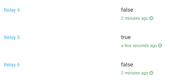
After running the chain, we can click some relays on the UniPi control panel and see how it is reflected on Cloud4RPi.
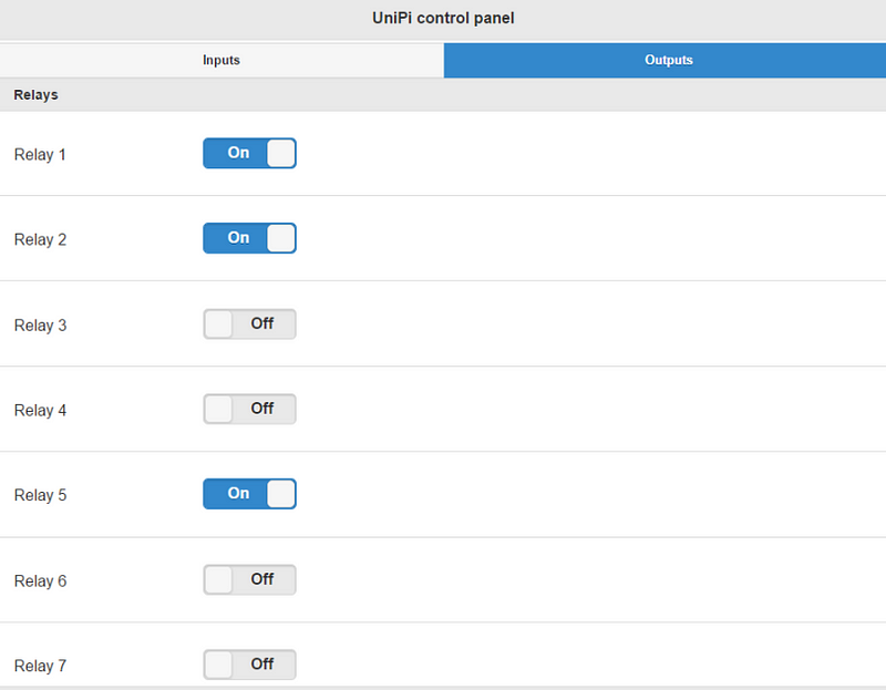
On the Cloud4RPi Control Panel, we can use the Switch widget for relays.
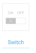
This widget can display a boolean variable and send commands for changing its state: a very useful tool for controlling our relays. The control implementation in Node-RED assumes subscribing to the devices/{token}/commands MQTT channel. You can control UniPi relays using the HTTP or WebSocket. Both options are OK, but I prefer WebSocket, because this protocol assumes sending headers once instead of sending them in each request. This will reduce the network load and increase the efficiency, especially when the Node-RED is running hardware separate from UniPi.
I’ve connected the MQTT node subscribed on /commands channel to the jsonnode, which creates a JSON object from an MQTT message:

Then, I’ve connected the JSON node with the function that converts the MQTT message to a WebSocket command:
for (var var_name in msg.payload){
    if (var_name.indexOf('Relay ') >= 0){
        return {
            cmd: "set",
            dev: "relay",
            circuit: var_name.split(' ')[1],
            value: msg.payload[var_name] ? "1" : "0"
        }
    }
}
Finally, I connected the function node to the WebSocket node.
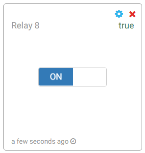
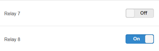
After running the circuit, I created the required Switch widgets and tested how they work on receiving and sending commands. Everything worked correctly. I saw the widget changes when changing the state in the Control Panel.
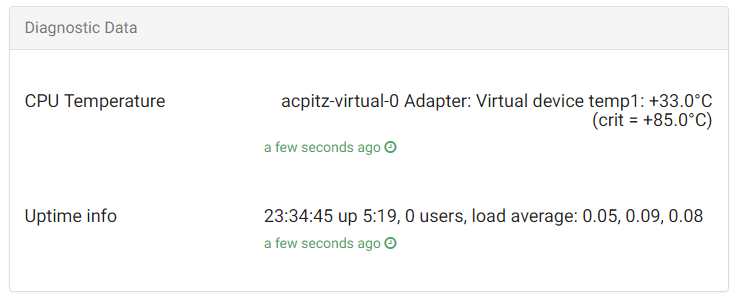
Cloud4RPi has an MQTT channel devices/{token}/diagnostics for device diagnostics. This is a convenient tool that allows you to send some variables reflecting the device state to the cloud and see their values on the Control Panel.
For example, I’ll send the CPU temperature and system uptime.
Node-RED has an exec node:

It can execute an arbitrary bash command and return its result.
Let’s use this node to fire commands every 30 seconds. Two chains are required to get the values and save them to a special Node-RED storage called flow, since these values should be sent to the devices/{token}/diagnosticsMQTT topic later.
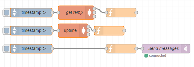
It’s important for the sending interval to be greater than the requesting interval, because the requesting node should have time for collecting data before it is sent.
The CPU temperature can be acquired using the sensors command, and the uptime — using the uptime command.
The function nodes located after the exec nodes are used to store the values. They contain the following code: flow.set(‘cpuTemp’, msg.payload) for temperature, and flow.set(‘uptimeInfo’, msg.payload); for uptime.
The message-shaping function contains the following code:
return {
    payload: {
        "ts": new Date().toISOString(),
        payload: {
            "CPU Temperature": flow.get('cpuTemp'),
            "Uptime info": flow.get('uptimeInfo') || ""
        }
    }
}
In a minute after starting, we can see the diagnostic data on the Control Panel:
I’ve made a frame for the device from timbers found in my larder, then attached a DIN-rail and nine sockets to it on screws. The device itself fixes on the rail along with the circuit breaker and the terminal block. One of the sockets has constant power for the UniPi adapter, other sockets are plugged to the relays.
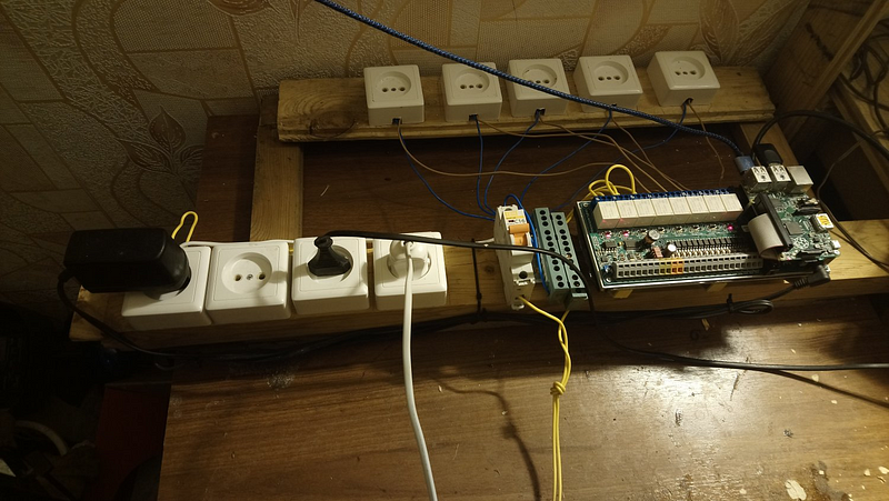
At this moment, the device controls lighting and watering, implements the “climate-control” in terms of heating (currently not required since it’s warm outside). My future plans include automatic ventilation and humidity maintenance.
Currently, we can determine what’s going on with our device from any Internet-enabled part of the world, collect data from sensors and even control the device.