 Litan Virgil
Hardware
Initial design
Note: Since the time I wrote this I continuously improved the design, so in a few places I will discus the initial decision versus current version. Also, if you check out the repository, there'll be the current state of the project.
So, first things first: I needed a datasheet of the VFD. Easy, right? Well, not really. After lots and lots of research I was able to find a blog post about those tubes and the related pinout . It was sufficient in order to understand what is needed, namely 20V voltage supply for the grid and segments and 1,5V for the filament.
Furthermore, in order to make it as easy as possible I chose an ATmega328 to play the role of the brain for this system. In order to keep the time accurate and preserve it throughout power-offs, an RTC with a backup battery was needed.
As the MCU doesn't have enough pins to drive each segment of each tube I decided to apply the widely-known technique of multiplexing. In order to do this, a transistor has to be added for each tube to turn it on and off, besides the transistors that drive the segments - but we`ll get to the driver design later on.
I wanted a minimal user interface so I decided that 1 push-button should be enough to swipe through the functional modes, namely hour and minute display, day and month display or simply year display. Also, a buzzer should be useful for... well, I don`t really know yet, but I will surely find its utility on the long run. Alarms, maybe? Also, given the fact that it's the IoT era, the UART port of the MCU should remain accessible if I later decide to incorporate Bluetooth / WiFi / GPS into the project.
Lastly, I wanted to design 2 custom PCBs which ended up stacked inside the final product (in order to obtain a more compact and retro-looking clock).
So, the main components of the project are:
- 4 tubes and their corresponding drivers;
- 1,5V power supply;
- 20V power supply;
- 5V power supply (for the MCU);
- RTC chip and backup battery;
- ATmega328 with ISP connector;
- Buzzer driver.
The tubes and their drivers
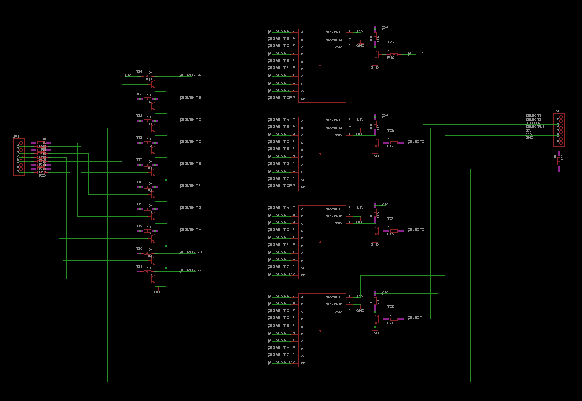
I decided to use basic NPN transistors in order to pull down the pins of the segments that would be otherwise pulled up by the 10K pull-up resistor. Also, a 1K resistor was needed between the MCU pin and the base of the bipolar transistor. The same strategy was used to drive the grid pin of each tube that acts like an enable pin. All corespondent segment pins are connected to be multiplexed (a more detailed view, use the link to the project repo).
The first issue with those "well-documented" tubes it was that there was no footprint to be imported in Eagle. So what now? I had to make it by myself. I measured the size of the tube and drew the shape of it and then I had to place all 13 pads in a circle, equally spread-out. After trying to do this by hand I remembered that, hey, I`m a programmer, so I wrote a short C program that wold generate a script for Eagle that would place all the pads correctly. Here it is:
#include <stdio.h>
#include <math.h>
int main(void){
    float i;
    for (i = 0; i < 3.141592 * 2; i += 3.141592 * 2 / 13) {
        printf("pad (%f %f); ", sin(i) * 3.1f, cos(i) * 3.1f);
    }
    return (0);
}
After putting all the pieces together, I obtained the PCB responsible for holding and driving the VFDs:
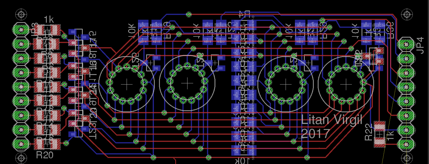
You can also see the pins that interconnect the boards on both far left and far right of the design.
Power supplies
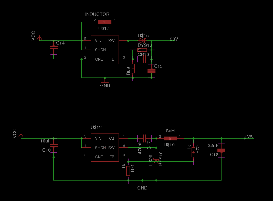
Switching
In order to provide 1,5V (1,5V turned out to be to much, as you can see in this video, the filaments turn red-hot) and 20V I needed a buck converter and a boost converter. Regarding the design of the supplies, I followed the guidelines found in the data sheets and chose the appropriate components. Also, I needed to create my own footprints for some components, you`ll also find those in the repo.
 Linear power supply
For providing clean power to the MCU, a linear regulator was needed, as the already existing two switching power supplies were creating a lot of noise on the power lines. So, I chose the good-ol` 7805 (now I decided a more up-to-date IC would be more suitable, so I chose the ams1117) and a bypass capacitor close to the MCU and the RTC IC (in the current version more pads for capacitors were added, just in case). Also, in case I (or anyone who uses this design) decides that the input voltage of the clock should be 5V, I added a pad between the VIN line and 5V line, so a 0 Ohm resistor can be added.
Real-time clock
Obviously, if I design a clock, I want it to be as accurate as possible, and use a real-time clock IC that would keep track of time even when turned off. I saw the popular RTC module from sparkfun and I decided to reproduce the circuit in my project (they even provide the Eagle files for this).
The controller
I chose the popular ATmega328 as the main controller because it's easy to use and configure, all that is needed is the SPI-ISP connector (2 x 3 pinhead). More on this subject will be discussed in the Software section.
Buzzer driver
Lastly, the buzzer driver. Nothing fancy, just a NPN bipolar and a resistor.
PCB manufacturing
As I wanted to design a compact system I chose to do the PCB`s at a factory. I need something that would allow small traces (6mil) but also do them cheep (beeing the first iteration, anything could go wrong, and I didn`t wanted to throw away to much money on something that could be flawed) so I chose a chinese manufacturer, more precisely PCBWay. I waited about a month or so, but the PCB`s turned out fine. A small issue I had, if a added some milling to the design to get the two boards (driver board and logic board) separated they considered it's a panel, so charged me extra, but as I was going cheap my trusty dremel handled this :D.
Software
The software is currently in the let's-see-if-all-hardware-works-ok state so there isn`t much to talk about. Mainly, I tested the RTC (works ok) and the tubes drivers, and here comes the main issue: I noticed that even if the "enable" of a tube (the grid) is low, the segments still light up a little bit, so when different digits are displayed a sort of ghosting effect appears, and it doesn`t look that good (see the video).
The code is non-optimized (for the sake of simplicity), but what it is mainly doing is storing the to-be-displayed characters in an array and when a method is called (namely "iterate()") the values of the segment pins are changed accordingly with the index of the tube, and that tube is enabled, and the rest are shut down.
This can be improved in a few simple ways: use directly registers for assigning register values for example, or more efficient indexing, but that was not the purpose (for now).
Due to some issues with the 20V power supply, a parasitic resistance across the feedback network caused the output to become 30+V and burned the tubes. I have to do some research - regarding whether or not should I use a dedicated driver, should I add a negative voltage source in order to get rid of the ghosting effect, should I use a transformer to get that negative voltage, etc - and because I don`t have that much time now (due to university assignments that need my attention) I decided to shelf the project. So, any suggestions are welcomed until I start working again. (: