 James Ots
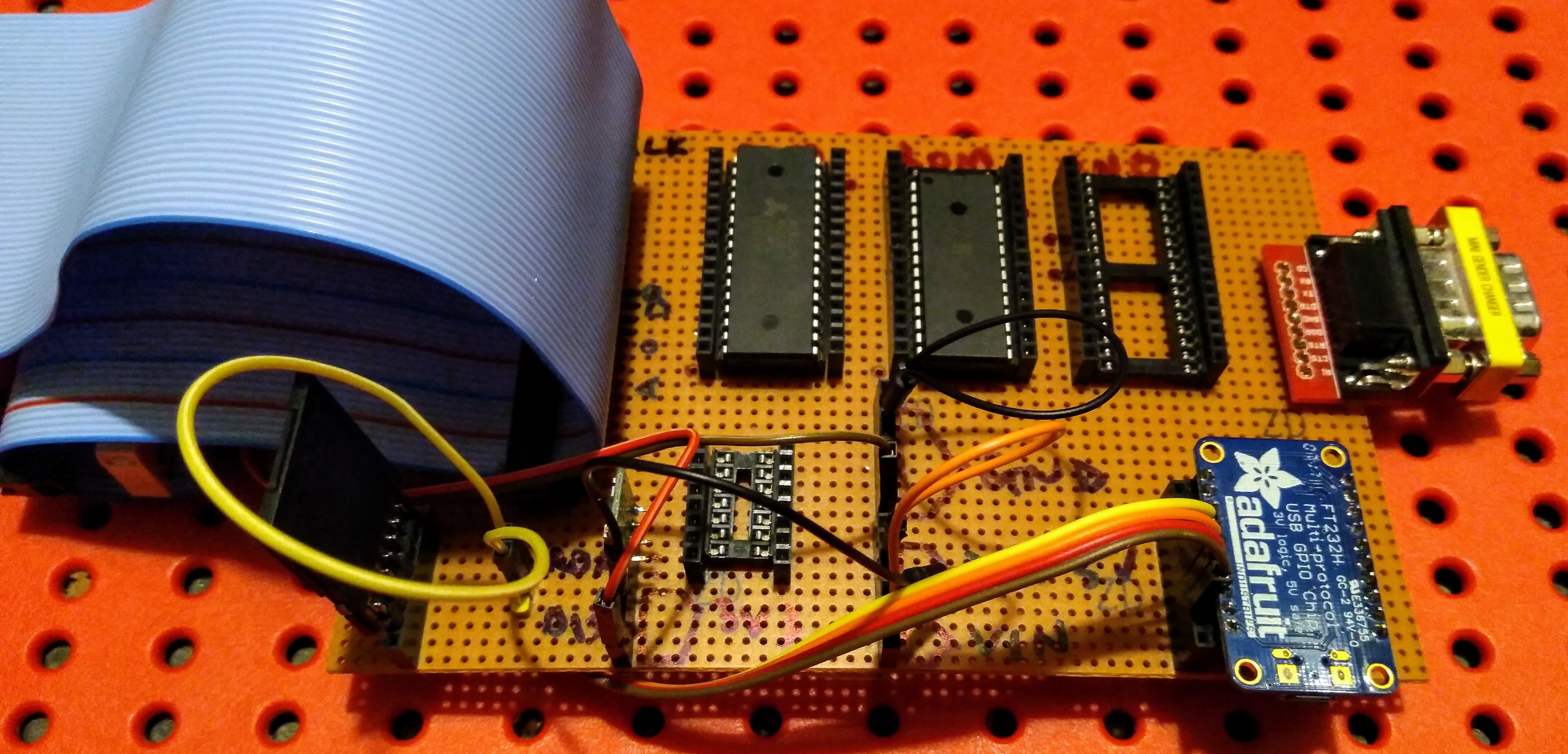
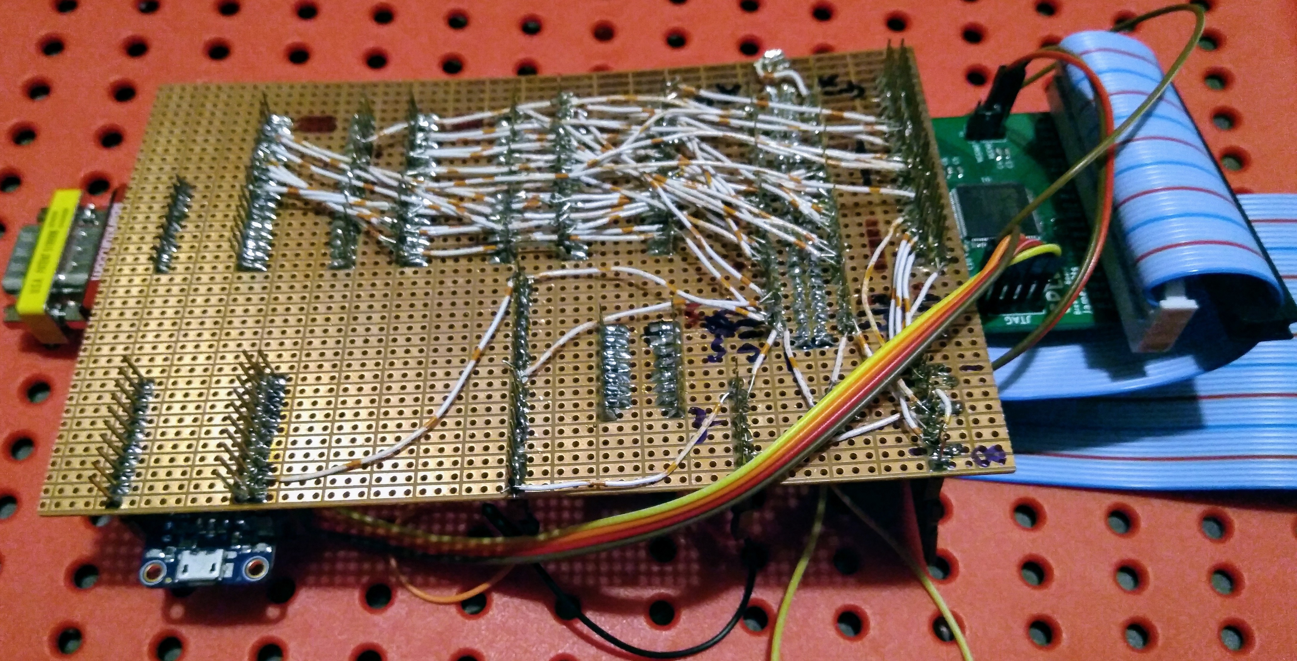
I've spent the last week moving my circuit from breadboard to stripboard. It's taken this long because I kept getting bored of soldering lots of tiny wires and going to do something less monotonous. But I got it all wired up in the end, and it's working too, although it took a bit of debugging to get there. Initially I missed off a few essential wires — for example, I'd forgotten that I'd wired the Z80's RESET signal into the CPLD's GSR input on the breadboard. Then, even when I was fairly sure all the wires were in the right place, it still refused to work. So I used a multimeter to check if there were any shorts between adjacent pins, and discovered that D2 and D3 were shorted by a loose ball of solder. After removing that (and giving the rest of the board a blast of compressed air for good measure), it all seems to be working perfectly.
It's a little bit Heath Robinson though. I've used stackable headers all over the board, which means that I get a socket on top, and nice long pins underneath to solder wires to. Then there are two long pin headers at the end of the board — one has my CPLD breakout board connected to it, and the other has the 50-way cable from the PCW connected to it, which then loops around and connects to the underside of the CPLD board. It's messy, but effective. And it frees up my breadboard for more experimentation. Of course, when I get a PCB fabricated then it'll be done properly!
Here it is: (Oh, and I haven't done quite finished the sound or video circuitry — I wanted to be sure the RAM, ROM and SD card worked first).
Discussions
Become a Hackaday.io Member
Create an account to leave a comment. Already have an account? Log In.