 jason.gullickson
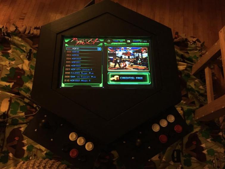
After six iterations of corner designs, the display is securely attached.

The top of and the bottom of the cabinet are painted and overall it’s starting to take its final form.
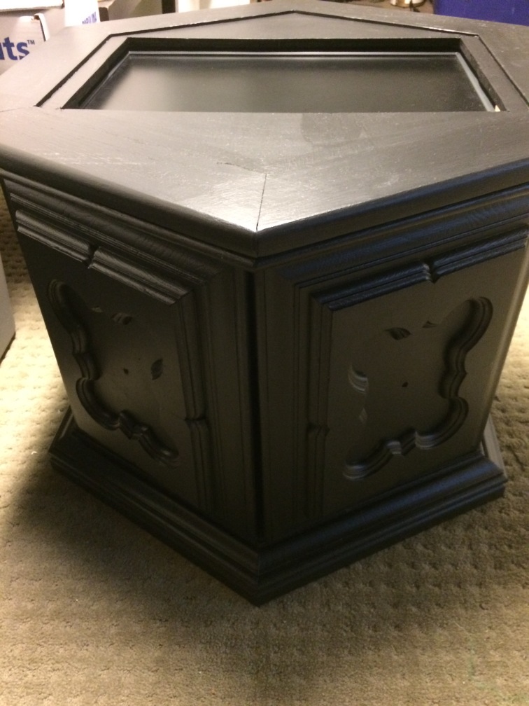
Starting with a table saved us a lot of cabinet-building time, but we need a place to put the player controls so there was still some carpentry to do.


With the control boxes completed it was time for my favorite part, the electronics.

I made some assumptions about the electronics hardware based on the fact that were are using a JAMMA-based module as we did with DONOR-1. However, the new module has a few significant differences (other than a lot more games).
The first difference is that it doesn’t have a Molex-style connector for the power supply. Another difference is that there’s no DIP switches to configure things like the display orientation. Luckily neither of these turned out to be a problem. I was able to use he power lines on the JAMMA connector with the power supply I had picked from the parts bin, and a few minor modifications to the corner clamps allowed me to flip the screen to work with the fixed orientation.
One helpful difference is the fact that the board not only has a built-in audio amplifier but also a physical volume control (instead of software-controlled volume like DONOR-1). I didn’t think the new board had an amp built-in so I thought that would be an additonal piece required for this build. One less thing to find a home (and power) for!
Wiring the JAMMA harness to the controls can be tedious because the documentation isn’t great (just getting the orientation of the connector right can be difficult), and there’s not enough colors to make every wire a unique one. I thought this would be doubly-hard this time around because we have two sets of controls. However, it turned out that the harness was wired cleverly in that the same color wires are used for both sets of controls. This doesn’t help much with the first controller but it lets you use the first controller as a reference when wiring the second. This makes wiring the second controller a very quick and error-free job.
…assuming you wire the first controller correctly…
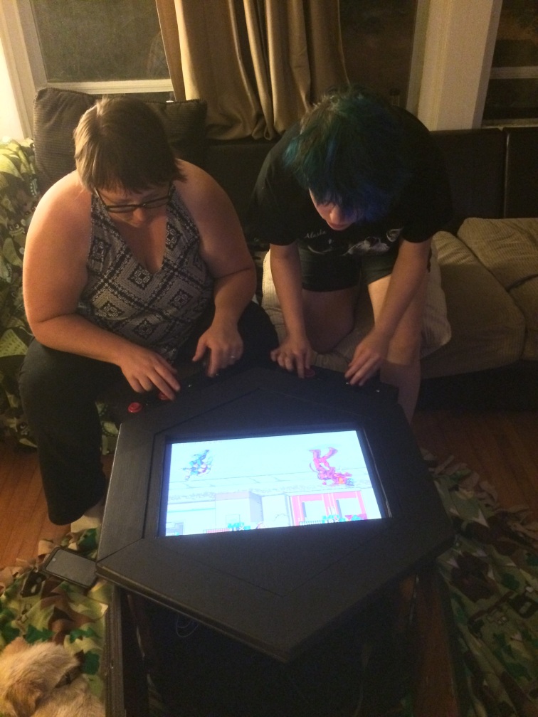
Once all the necissary connections were made it was time to apply power and pray to the blue smoke gods to stay home today. The fates were on our side and the display lit up with no indication of fatal-levels of wiring mistakes.

There was one small error which reversed the up and down direction of both joysticks, but a quick wire swap and all was in order.
At this point the system is playable, but there is more work to do. The most obvious missing piece is a place to mount the 1 & 2 player start buttons. There wasn’t enough room to cram them into the control boxes, so we’ll need to find a different place to mount them. We also need to replace the temporary speaker with something more permanent (and more securely mounted), clean-up the internal wiring and mount the AC power switch/input/fuse plate.
There’s also additional design work to do and we still haven’t decided exactly how we want it to accept donations yet…
Still, there’s been a lot of progress in only a couple weeks (and really only a few working days in that time). We’re still learning, but the experience of building DONOR-1 has definitely had an impact on how well this build is going, even if it’s very different from the first.
Discussions
Become a Hackaday.io Member
Create an account to leave a comment. Already have an account? Log In.