 deʃhipu
The PCBs for version 5 arrived. It took some more time, because I ordered them from China — this time I wanted 10 red PCBs, to make a bunch of prototypes that I can give to interested people for testing.
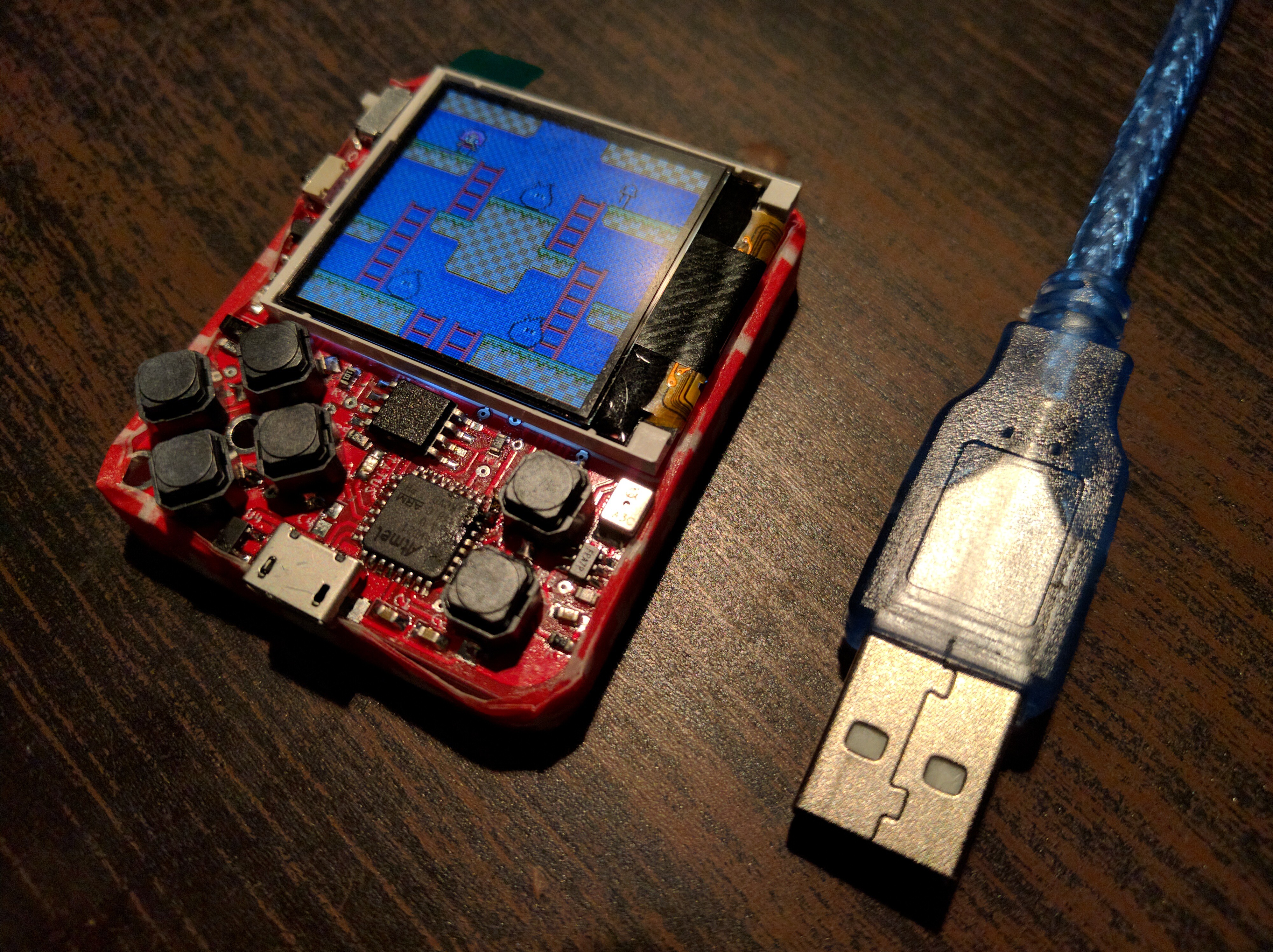
Here I also experimented with using half of an SD card box as the case for the back, held together with some tape. Maybe not pretty, but functional. I might actually go with those boxes, if I figure some way to attach them better.
There is one annoying problem with this version. While the screen display I used in the first prototypes (and re-soldered to every new prototype) worked without issues, the new displays I got refused to get initialized for some reason. I tried lowering the SPI clock, adding all kinds of delays, etc. — all for nothing. Then I soldered some wires to the MCU pins and connected a logic analyzer to see what the problem is, and suddenly the screen worked! There must be some noise on the pins when the SPI peripheral resets, and since the CS pin is hardwired down, that de-synchronizes the communication. The weak pull-downs of the logic analyzer are enough to avoid that noise. As a fix, I added a 200kΩ pull-down resistor to the clock pin — fortunately it's on the corner of the MCU — and that seems to make the display work reliably.
Another problem with this and previous versions is the audio circuitry. I didn't really have much space for it, so it's all tucked next to the fire buttons. The problem with this is that it's really easy to touch the amplifier's input pin with your finger, which results in unpleasant noise.
A third problem is that the charging LED switches on whenever you connect USB power, no matter if the battery is connected or not. Ideally it would only come on when the battery is charging.
So of course I had to make version 6, which has all those problems (hopefully) fixed:
- I swapped places of the battery charging circuit and the audio circuit. Now the amplifier and speaker are on that narrow strip next to the screen, where they are safe from fingers, and the charging circuit, together with the led, is in the lower right corner. As a bonus, there is a mounting hole there too now.
- I disconnected the CS pin from GND and connected it to one of the MCU pins. This way I can synchronize the communication by releasing the CS pin once in a while.
- The charging LED is now powered from the battery. No battery — no light.
- There are some doodles on the back:
Discussions
Become a Hackaday.io Member
Create an account to leave a comment. Already have an account? Log In.
If you have a pin left on the microcontroller, I would wire the CS pin as well. For the clock pin: probably this is a problem when powering up the thing, because then all microcontroller pins are configured as input and would explain why the pulldown works. Using the extra CS pin would solve this, too, and would be more reliable, because usually the SPI bus on the receiver resets the data input shift register and clock count on falling CS edges, so it can't go out of sync, if you set CS to high when idle, and only low before sending a command.
For the PCB mounting in the SD card box: maybe try hot glue, if you have a rechargeable battery?
Are you sure? yes | no