 Chris
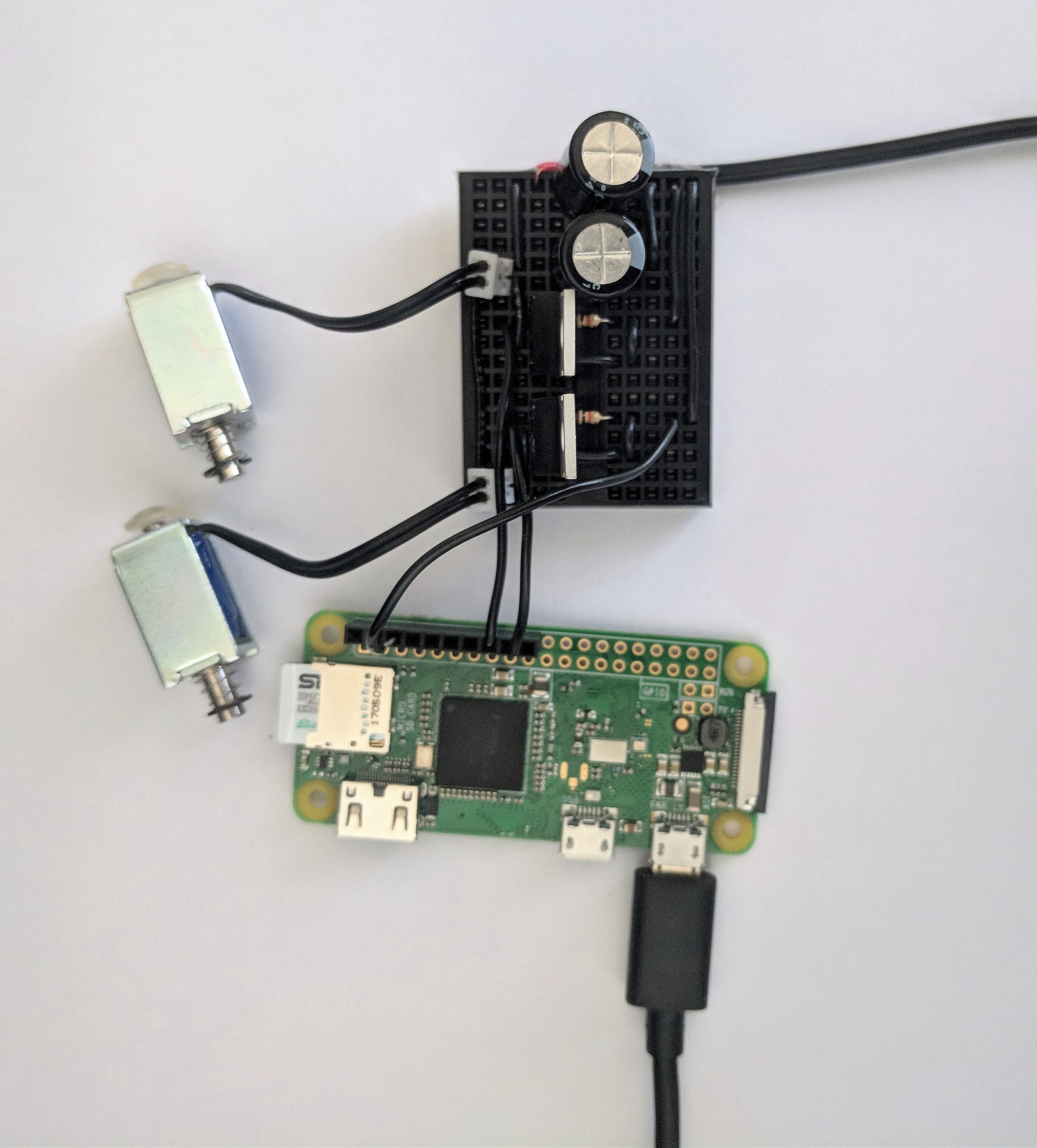
ChrisThe circuit here is straight forward. I’m using a basic MOSFET-as-a-digital-switch configuration like what is shown here (http://www.learningaboutelectronics.com/Articles/N-channel-MOSFET-switch-circuit.php). I have added a 10k Ohm resistor between the gate and ground to make sure it is pulled down when not activated. I also use 2 1000uF bypass capacitors on the power rails for good measure. This isn’t particularly necessary though because I’m using a separate power supply for the solenoids and the RPi. If I wanted to be particularly rigorous, I could put a few hundred ohm resistor between the RPi and the gate to prevent any weird oscillations due to the gate capacitance, but considering our switching speed is about 1Hz, as opposed to the 1Mhz these can operate at, I’m not concerned.
We also need a ground connection between the RPi and the breakout boarding to make sure all parts of our circuit use the same ground reference.
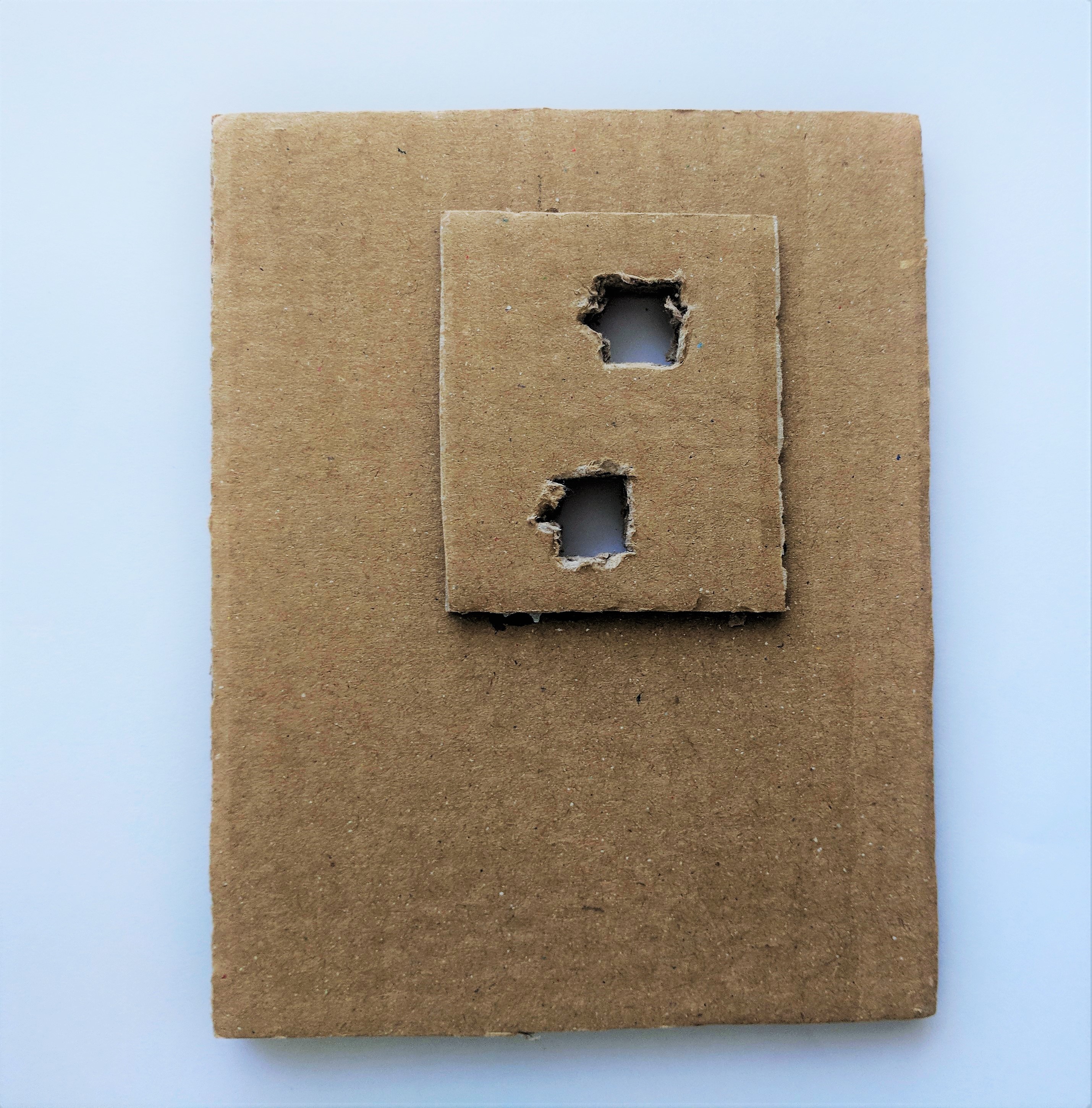
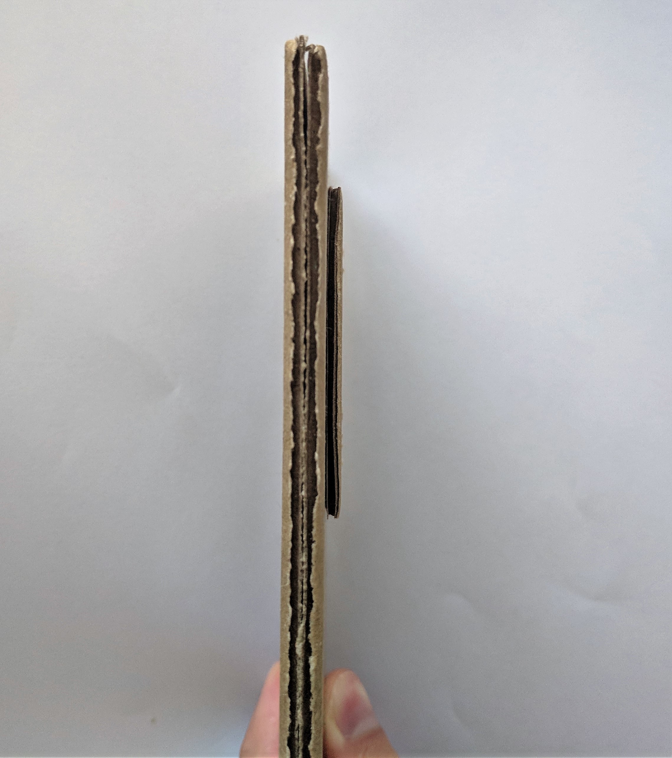
You’ll notice that I’m struggling super hard on the equipment here while I’m out of the states…only black, hand-cut jumpers on a black board that’s barely large enough and no socketing. Also, the mount to attach everything to the touchscreen is simply some cardboard I've glued together
Since writing this, I've upgraded to a 12v power supply for the solenoids because you really need hammer on the touchscreen. 5v would be perfectly find for any modern capacitive touch screen or even a not crappy resistive touchscreen.
 |  |
 |
Discussions
Become a Hackaday.io Member
Create an account to leave a comment. Already have an account? Log In.