 Christoph
Since there are many circuits which do something very similar to what this circuit should do, I'll have a look at some of those first.
From https://electronics.stackexchange.com/a/140416/18496
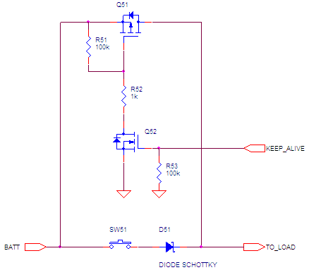
This one seems to be a bit minimalistic, but doesn't have anything I don't need. There's no "press and hold button to switch off again" for example. OTOH, it doesn't feature a sense output to be read by an MCU.
Next one is again from stack exchange:
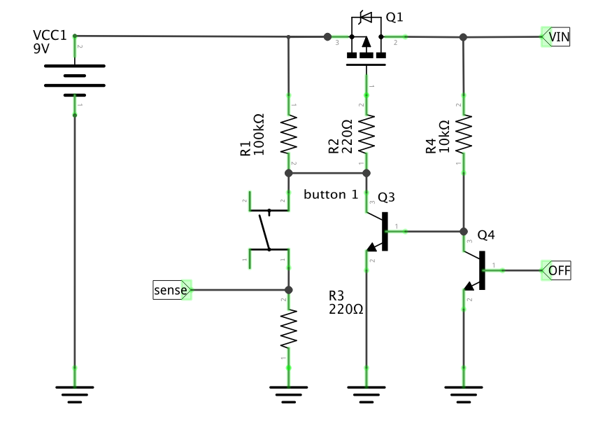
- Different approach without a shottky in the way when compared to the previous one
- there is a sense output that didn't get the love it needs.
- Unnamed R (below the push button) must be matched to battery voltage and whatever should be connected to sense
- Q4 is used to use an active "switch off" pulse rather than a constant "keep alive" and it would need a current limiting resistor for the base.
There was a lot to find in the eevblog forums. This thread for example. From that one:
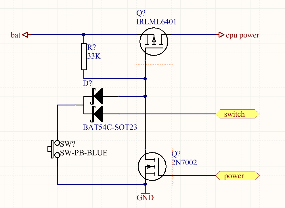
That looks simple enough and it might do what I need. Some things to consider:
- "switch" (or "sense" in the above notes) is active low and will need a pull-up. No big deal, and that can even be an mcu's internal pull-up.
- There might be a voltage regulator downstream of "cpu power"
- There will be large caps downstream of "cpu power"
- "power" can probably be turned from constant active-high keep-alive to pulse active-low shutdown, but that might come with some delicate timing issues
- I think the "power" transistor needs a gate pulldown resistor for the keep-alive configuration
- Is the upper diode really necessary? Wouldn't the lower one suffice?
Discussions
Become a Hackaday.io Member
Create an account to leave a comment. Already have an account? Log In.