 Paul Andrews
I'm dealing only with the simulation here. I'll get to actual component selection when I discuss the prototype and the finished board.
Input Voltage
I chose 5V as a target input voltage. I could run the simulation at 12V, but that isn't my target input, that is just something I would like my power supply to be able to handle. I also want it to handle a LiPo battery, so I need to run the simulation at 3.7V too.
However, the big problem with the first simulation is that there is no internal resistance specified for the voltage source. A real voltage source does have an internal resistance, and this causes the input voltage to drop as more current is drawn. I change the simulation to use an IR of 0.5 Ohms. This seemed to produce a realistic drop in the input voltage.
Output Capacitor
The output capacitor (C2) serves to smooth out the ups and downs of the output voltage by storing charge during the on phase of the diode and providing it when it is in the off phase. If the capacitance is too small, the output will have a ripple. If it is too large, it will take too much power to charge. 0.22uF is lower than most designs seem to recommend. I tried up to 1uF in the simulation. The only effect was to lengthen the ramp-up time, so I stuck with 0.22uF.
Capacitors have a resistance called ESR (Equivalent Series Resistance). This affects how quickly it can discharge and, of course, dissipates power. The lower the better. My model used 0.025 Ohms.
Rsense
The transformer model provided by Wurth actually models things like saturation current, so I was intrigued as to how much I could affect the simulation by varying this resistor. I dropped it as low as 0.02 Ohms, which had no effect. I raised it 0.1 Ohms and this completely destroyed the circuit's ability to generate a high voltage. So I stuck with 0.05 Ohms!
Input Capacitor
This capacitor smooths the input voltage by charging while the MOSFET is off and providing power when it is on. Like the output capacitor, you want to have a low ESR so that as much power is delivered as fast as possible to the transformer. I left this value completely alone and defined an ESR of 0.074 Ohms.
Ccomp and Rcomp
And so we come to loop compensation. Do you know what Bode plots are? How about poles? Zeros? Right half planes? No? Me neither. Basically, what these values do is to control how quickly the chip responds to changes in load to keep the voltage constant. If it reacts too quickly the output voltage will jump up and down. If it reacts too slowly, the output voltage might never adjust to the load before the load changes again. I messed with these values. If I increase Ccomp (to say 220nF) the simulation overshoots the target, then drops, then overshoots. etc. If I decrease it, there is a ripple in the output. In other words, 22nF seems about right. Changing the resistance has no noticeable effect.
If you are interested, this is all dealt with in note AN-1286. There is an online bode plot tool here or here. I did try and use the math to calculate the ideal values. I worked through the example in AN-1286 using excel and one of the online bode plot calculators, but my numbers didn't tally with theirs. I would be interested if someone could do this, though it doesn't really affect the actual circuit. I asked the folks over on Neonixie about this. They said 'Just build the prototype!'.
The MOSFET
Finally, the MOSFET. Nick de Smith has some recommendations:
Select the FET for low RDSon, Qg and Coss
So I did. I changed the FET to an IRL640A. Basically, again, we want the MOSFET to consume as little power as possible.
However we need some other characteristics:
- Vds needs to be able take the reflected voltage from the secondary. The IRL640A has a Vdsof 200V!
- Vgs(th) needs to be significantly below the input voltage. This value is the threshold at which the MOSFET starts to turn on. It actually completely turns on at some value above this. The IRL640A has a Vgs(th) of 1 to 2 volts.
It eventually turned out that this wasn't a great choice. We'll get to that.
Sadly, there seems to be no LTSpice model for the IRL640A, so I had to make one using this tool kept at the Yahoo mail group.
Results
The results aren't much different than the initial circuit. The output voltage curve is pretty much identical. This is the reflected voltage (Vds):
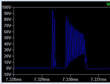
There's still ringing, but it's a little bit better. Peak voltage is at least below 100V!
Let's take a look at the current through the primary side:
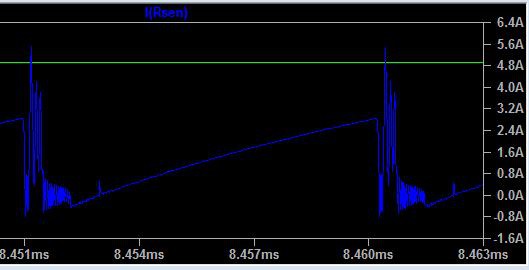
By my reading of the Wurth data sheet the current can go up to around 6A before the transformer saturates. So we're good, but there is clearly ringing going on here too.
We'll address that in the next log.
3.7V
If I run this using 3.7V, I get this:
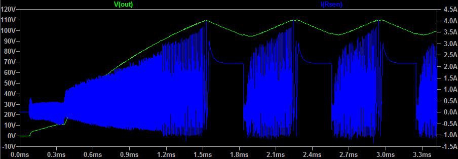
This is not good! The MOSFET apparently stops switching. The IR of 0.5 Ohms is excessive for a LiPo. It turns out that this was pulling the input voltage below 3V, which is too low for the IC (not sure why this means the MOSFET apparently stays on, but whatever. The internal resistance of a LiPo is typically in the mOhms. Anyway, setting a more realistic IR for the input fixes this problem.
Discussions
Become a Hackaday.io Member
Create an account to leave a comment. Already have an account? Log In.