 Paul Andrews
I got my thermal camera, so the results are in! It looks like the peak temperature I have managed to get for the transformer is 129°F. Here are some pictures. The first shows the temperature of the transformer. This is when the power supply is producing 20mA at 200V with 12V in:
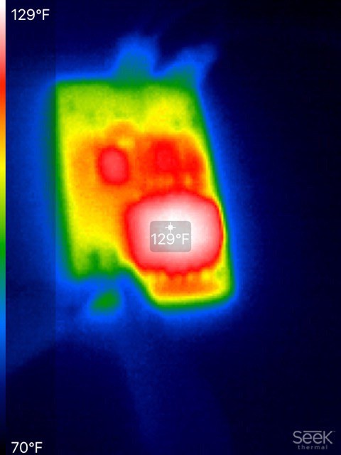
Next up, the controller:
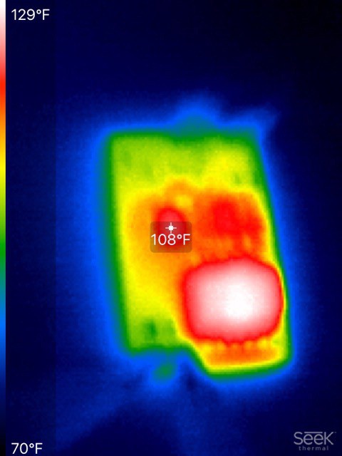
And next the MOSFET:
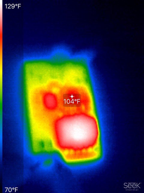
Is that OK? Well the data sheet for the transformer says:
It is recommended that the temperature of the part does not exceed +125°C under worst case conditions.
125°C is 257°F, so we are well under that. These measurements were taken with an ambient temperature of around 70°F. We could expect worse behavior in a closed case, but I think we may still have some headroom, so it could be that the current sense resistor value that I chose could be reduced some. I will try this with a 0.04Ω resistor and check the temperatures again.
I will list the final component values in a moment, but for now here are some performance results:
| 12V | |||||||||
| Rload (K) | Vout | Iout (mA) | W | Vin | Iin (mA) | W | Eff | ||
| 20 | 199.6 | 10.40 | 2.08 | 11.96 | 238 | 2.85 | 0.73 | ||
| 15 | 199.5 | 13.70 | 2.73 | 11.96 | 298 | 3.56 | 0.77 | ||
| 10 | 199.2 | 20.00 | 3.98 | 11.94 | 415 | 4.96 | 0.80 | ||
| 20 | 177.6 | 9.26 | 1.64 | 11.96 | 195 | 2.33 | 0.71 | ||
| 15 | 177.5 | 12.18 | 2.16 | 11.96 | 243 | 2.91 | 0.74 | ||
| 10 | 177.4 | 17.84 | 3.16 | 11.96 | 347 | 4.15 | 0.76 | ||
| 5V | |||||||||
| Rload (K) | Vout | Iout (mA) | W | Vin | Iin (mA) | W | Eff | ||
| 20 | 192.4 | 10.00 | 1.92 | 4.85 | 500 | 2.43 | 0.79 | ||
| 15 | 172.6 | 11.84 | 2.04 | 4.84 | 502 | 2.43 | 0.84 | ||
| 10 | 141.0 | 14.17 | 2.00 | 4.8 | 508 | 2.44 | 0.82 | ||
| 20 | 177.0 | 9.22 | 1.63 | 4.85 | 500 | 2.43 | 0.67 | ||
| 15 | 172.5 | 11.81 | 2.04 | 4.84 | 502 | 2.43 | 0.84 | ||
| 10 | 141.0 | 14.18 | 2.00 | 4.8 | 508 | 2.44 | 0.82 | ||
| 3.7V | |||||||||
| Rload (K) | Vout | Iout (mA) | W | Vin | Iin (mA) | W | Eff | ||
| 20 | 174.0 | 8.80 | 1.53 | 3.6 | 373 | 1.34 | 1.14 | ||
| 15 | 154.0 | 10.34 | 1.59 | 3.6 | 370 | 1.33 | 1.20 | ||
| 10 | 130.0 | 12.80 | 1.66 | 3.6 | 364 | 1.31 | 1.27 | ||
| 20 | 172.0 | 8.80 | 1.51 | 3.6 | 380 | 1.37 | 1.11 | ||
| 15 | 153.0 | 10.30 | 1.58 | 3.6 | 373 | 1.34 | 1.17 | ||
| 10 | 129.0 | 12.70 | 1.64 | 3.6 | 370 | 1.33 | 1.23 | ||
For each input voltage, there are two sets of numbers. The first set is for a Vout limit of 200V. The second set is for a Vout limit of 177V. Here are some takeaways:
- My measurements for 3.7V are clearly wrong somewhere, because they give an efficiency of > 1!
- Ignoring that, we are hitting efficiencies of between 70% and 80%, which is pretty good!
- We can get 20mA out of it if we put 12V in. We could probably get more, but my test equipment (such as it is) can't go lower than a 10K load without starting a fire. In fact, the thermal camera shows that my 10K load resistor was hitting 400°F as it is! Anyone want to buy me some lab equipment? 20mA will power just about any 6 tube clock.
- On battery, we can get 8mA out, which is enough for 4 to 6 small tubes. Which is fine.
- On USB (aka 5V), we can get roughly 12mA out at a decent voltage. That is good for a lot of tube types. If I can decrease Rsense, so I can get more current flowing, we could improve these numbers.
- The voltage regulation starts to fail as load goes up and input voltage drops. Again, I know from experience that if I can drop Rsense, I can get a more stable output voltage
So here is the final circuit diagram:
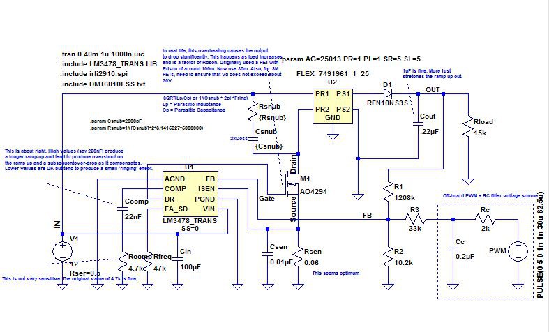
- The MOSFET is an AO4294. This has a 100V Vds and a very low Rds(on). Other options I tried tended to get a bit warm.
- Rsen is 0.06Ω.
- Rfreq is 47K.
- Rsnub is 249Ω
- Csnub is 360pF.
- The diode is an ES1FL R3G.
- The transformer is a Wurth ER11/5 - order code 749196141.
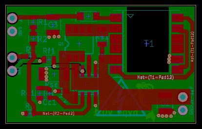
Here is a picture of the board layout:
Discussions
Become a Hackaday.io Member
Create an account to leave a comment. Already have an account? Log In.