 SUF
SUFI've many ideas in my had, what to build, what to experiment with.
A few of them involve using mains voltage directly. Some of this need to rectify and clean the input before using.
My lab power supplies are able to produce 60V DC maximum, what is clearly not enough for those experiments. A cost of a proper high voltage variable DC supply is enormous, and I don't need most of the features of it right now:
- Not need to be variable. My built circuits will have rectifications on its own. The input comes from mains anyways so this is the only voltage I need.
- Not need to be stabilized. Same concept as above.
- Not need to be isolated. I know, at this point the real professionals start to scream: IDIOT!!!! Let me explain why I'm not: 1. I've built a proper isolation transformer in the past. I can use it, when it is necessary. 2. My negligence: two way rectified mains after filtering in my country is around 650V DC. It is lethal anyways. If you make a mistake, it will kill you. It can't kill you twice because of the missing isolation.
So the plan:
Build a simple two way rectified supply with large can electrolytic capacitors (I bought 3300uF/500V ones for a good price. These puppies are huge).
Add necessary circuits for small panel meters to be able to measure, what is coming out from the circuit.
Add necessary circuit to discharge the capacitors. If they left unattended, they can still kill you after long time.
Add a special circuit I designed for it. It has two functions:
- Test if the equipment grounded to the protective earth (it is not a proper grounding test, but if your lab is properly grounded, it will tell you if you have cabling problems)
- Test the polarity of the incoming supply and change it if necessary. So the 0V output line of the equipment is always connected to the Null and never to the Line.
This circuit is still under development, so I don't know if it will work or not, but it isn't absolutely necessary for my power supply design. It adds some protection to the circuit, but nothing substitute the extreme care and the proper isolation.
I started to design this something like two weeks ago. Ordered the circuit board on the last Saturday. Actually it is already in my hands since Thursday, thanks to the extremely cheap, fast and high quality PCB manufacturer I found recently: ALLPCB (10 pcs 100x100 two sided boards for $5.49 delivered in 5-6 days - insane):![]()
Yesterday I had some time to populate the board: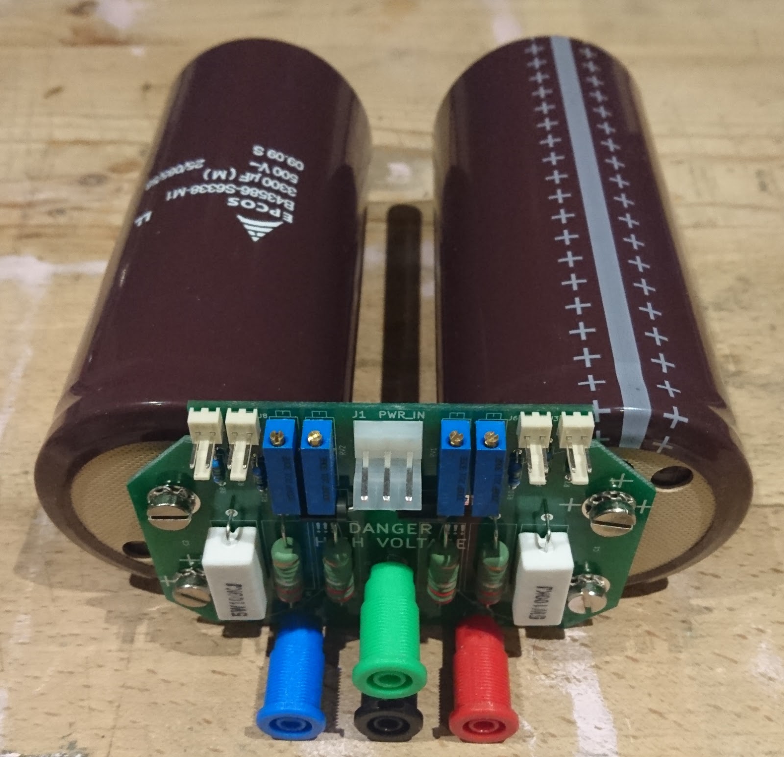

Those cans are huge, I told you.
Let see some measurement: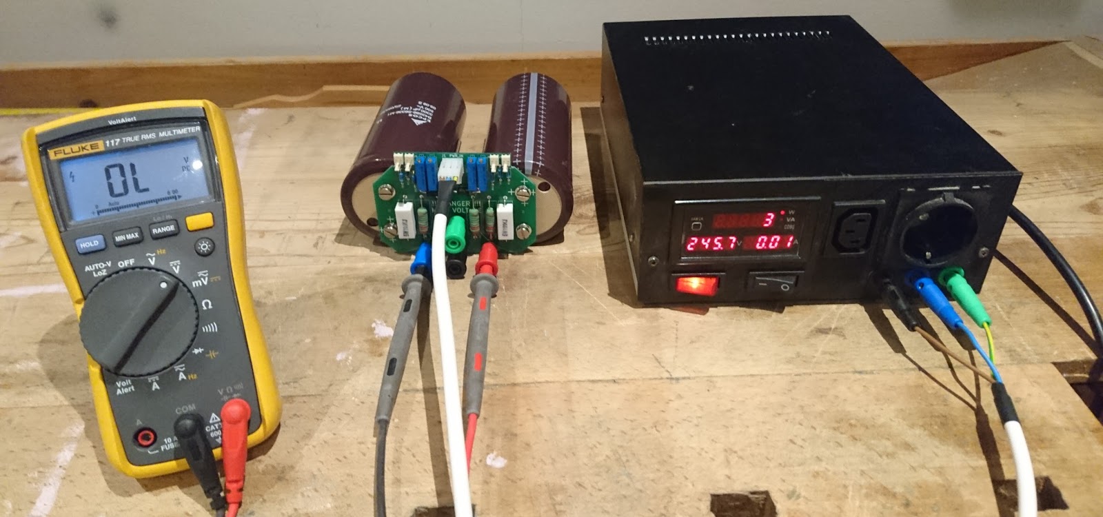
I've an isolation transformer, as I told before.
Ouch! My Fluke 117 unable to measure the output voltage. According to the specification it is able to measure until 600V. In fact it was working until 650V, but the supply is above this. Lets change to a 1000V rated tool:
So, the PSU works now. My first impression, that the 100k/5W resistors I connected in parallel with the capacitors are improper for draining them. It take quite a long time (several minutes) to do their job, and generating some (not to much) heat during the operation (the 3W consumption on the display of the isolation transformer). It is sufficient now, but I'm thinking to replace them to some active solution. (an AC Relay with some lower value/higher power resistors maybe).
This is it for now. Next is building into the enclosure, adding and calibrating the panel meters.
Discussions
Become a Hackaday.io Member
Create an account to leave a comment. Already have an account? Log In.