 Colin Alston
I drilled a 15mm hole for the SO239 connector in the umbrella mast and then hit it with a hammer for a bit to flatten it. Drilled some 2mm holes and drove some self tapping 3mm screws in. They held very well so I used the same for the rest of the build too.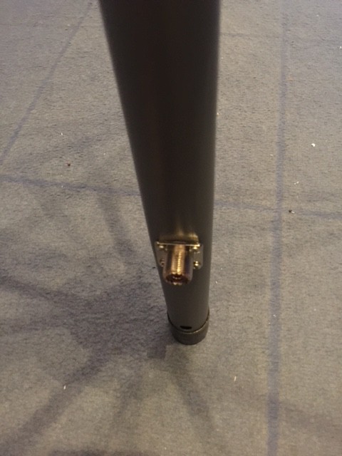

I soldered some RG58 coax to the connector and ran that up to the top of the umbrella. The pole is grounded at the bottom where the connector bolts onto it however the radials are insulated from the pole, so it was a bit tricky getting the right electrical length of the main radiating element while splitting out the coax shield to the radials.
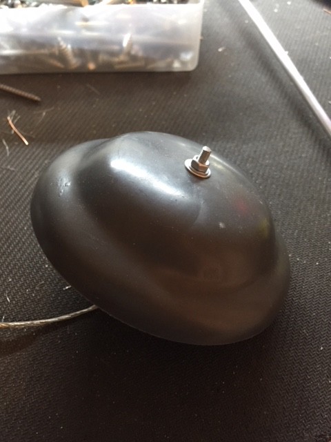
I also couldn't figure out how to reattach the top of the umbrella which holds the cloth without breaking the coaxes connection to the main quarter wave element. So I drilled and tapped an M3 thread into a 5mm X 470mm aluminum rod, that just left having a screw poke out the top of the umbrella for it to be screwed on or off.

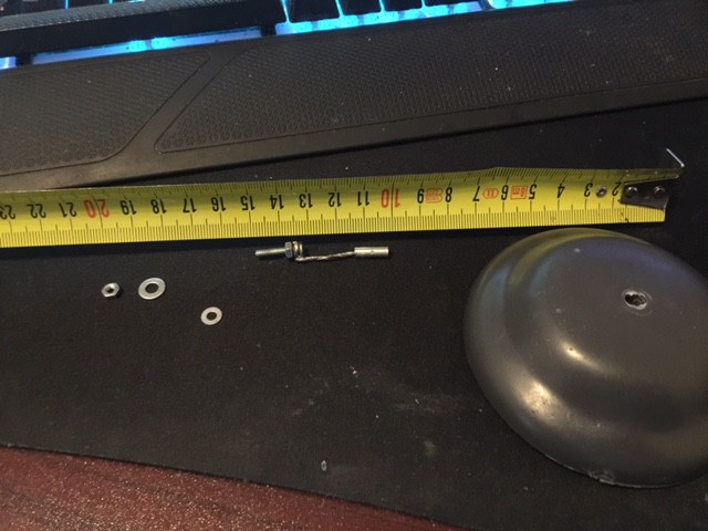
The reason my main element is quite a bit less than a quarter wave (500mm) is because there's about 30mm of the coax exposed between where the metal pole ends (and the coax is stripped and separated) and where the element screws into the top. It should be in total a touch more than 500mm, once I get an SWR meter I can trim it down - or even make a longer internal thread so it can be tuned by adjusting the screw.
All that remained at this point was connecting up all the ground radials with some copper wire and screws. First I filed off the paint around the holes and added a washer. I actually used a technique I saw on youtube for doing aircraft lock wires
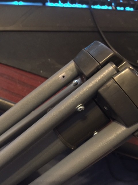

I forgot to take a picture of this while I was doing it but it's clearly visible how it works close up when unfolded.
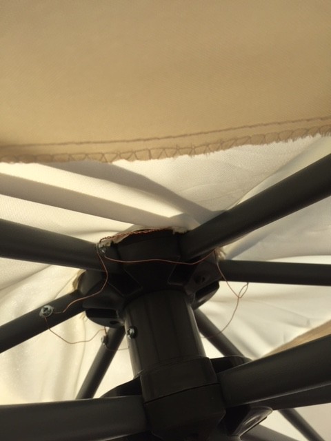
I drilled two holes either side of where the cloth holder (is there a technical term for this?) screws into the top of the umbrellas mast and twisted the coax shield in two halves just for some extra reliability I guess and perhaps more evenly distribute the ground into the radials.
All that remained was soldering the screw arrangement onto the coax, so I used a copper ferule and then twisted the screw a few turns in reverse so it would have less tortional stress on it when I screwed it back in.

And that's all she wrote


I tested it out for a bit, got good signal reports and was receiving well just with my UV5R handheld connected to it running on 145MHz
I still need to test the SWR, I'm not entirely sure if the length of the ground radials so who knows what's really going on. But I will update when I get a chance so thats all for now :)
Discussions
Become a Hackaday.io Member
Create an account to leave a comment. Already have an account? Log In.