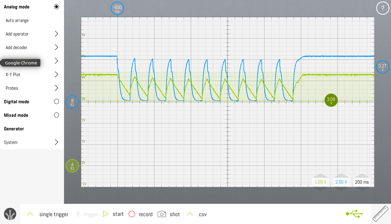
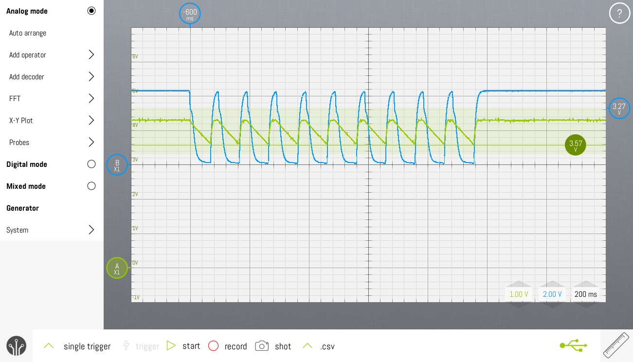
The nature of pulse dialing is such, that every pulse interrupts the power supply for 70ms. The pulse rate is 10pps, which means that during dialing, the MCU only gets power 30ms every 100ms. During the 70ms power gaps, the MCU has to survive on a 470µF capacitor.
Using sleep modes would allow us to choose a smaller supply voltage to reduce power consumption and to leave more headroom for the pulse dial telephone. Another option would be to decrease the elco and save cost.
Adding Sleep functionality in main loop
The rotary dial functionality is using Thomas Fredericks's Bounce2 library. To function properly it requires an update() function to be called regularly. By adding the update() function in the loop() function of Arduino, it's called every few tens of microseconds. No mechanical switch is that fast, so a lot of MCU cycles are wasted there. The following oscilloscope screenshots show VCC (green) and the GPIO connected to the main power entry point before the rectifying diode (blue).

The solution lies in adding a sleepNow() functionality in the main loop, which forces the MCU into idle mode when there's nothing to do. In idle mode, interrupts still wake the MCU.
Timer0 interrupt is in Arduino standard set up to be called every ms. So each ms, timer0 fires, which wakes the MCU. The MCU calls the Bounce2.update() and goes to sleep again. Simple but effective.

 Christoph Tack
Discussions
Become a Hackaday.io Member
Create an account to leave a comment. Already have an account? Log In.