 DrYerzinia
Rather than working on the Android app like I thought I would be I've been spending considerably greater effort on the hardware design. Lots of little things to think about. I'd been toying with the idea of using a buck boost converter to allow the AA TNC version to run off of Alkaline, NiMH, NiCD, and Li-Ion batteries. Is the ability to run on alkalines woth the extra dollar in parts costs. I decided to design it in. The only chip that I found that was both Buck-Boost and could go down to less than 1v for the boost was AS1337. I thought having LEET in the name it would work awesome but it had a few problems. Its maximum operating voltage is 4.5v. Enough for the Lithium-Ion batteries but not enough for the USB charge voltage. It's absolute maximum was 6v, so I thought I may as well see what happens if I gave it 5v.
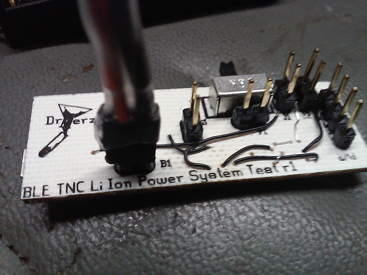
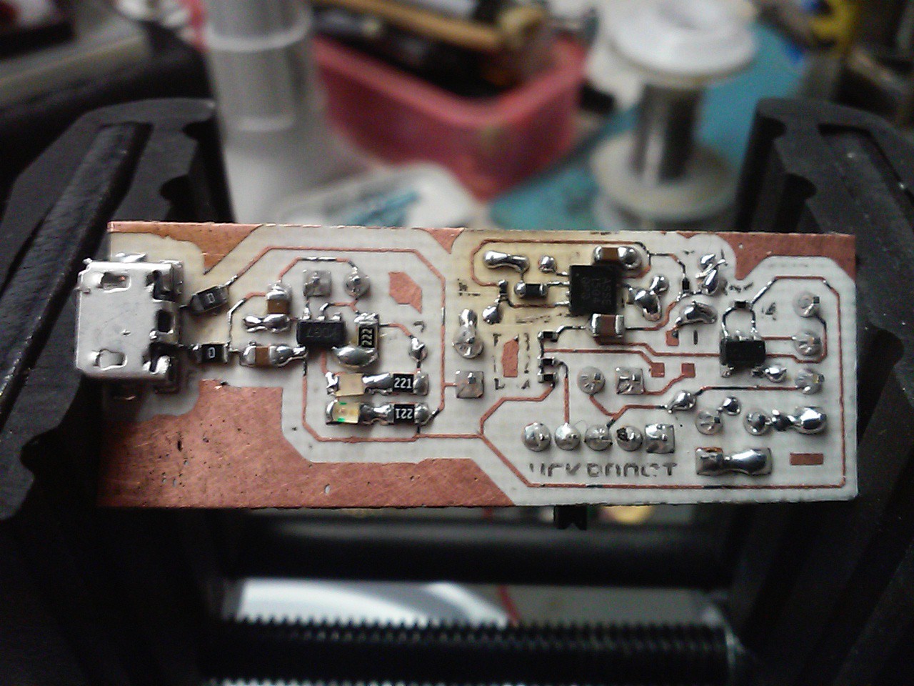
I designed a test power supply board with some jumpers to try and figure out what the best way to build the circuit would be. I added a 3.3v LDO regulator for USB power and figured I could just disable the AS1337, but upon further inspection of the datasheet I found out the disable mode had some properties that would screw me over. There are 2 models of the AS1337. Model A goes open circuit and puts battery voltage on the output when disabled. Model B shorts its output to ground when disabled. Neither was conducive to my design so I added a P-Channel Mosfet to actually shut off power to the regulator when USB power is connected.
This is where things went wrong. Unfortunately I forgot to check the Gate-Source voltage threshold when I selected a FET for the application. For it to work with a Alkaline cell I needed a Vgs(th) of less than 1 volt but I selected one that was 1.5-3.0 volts.
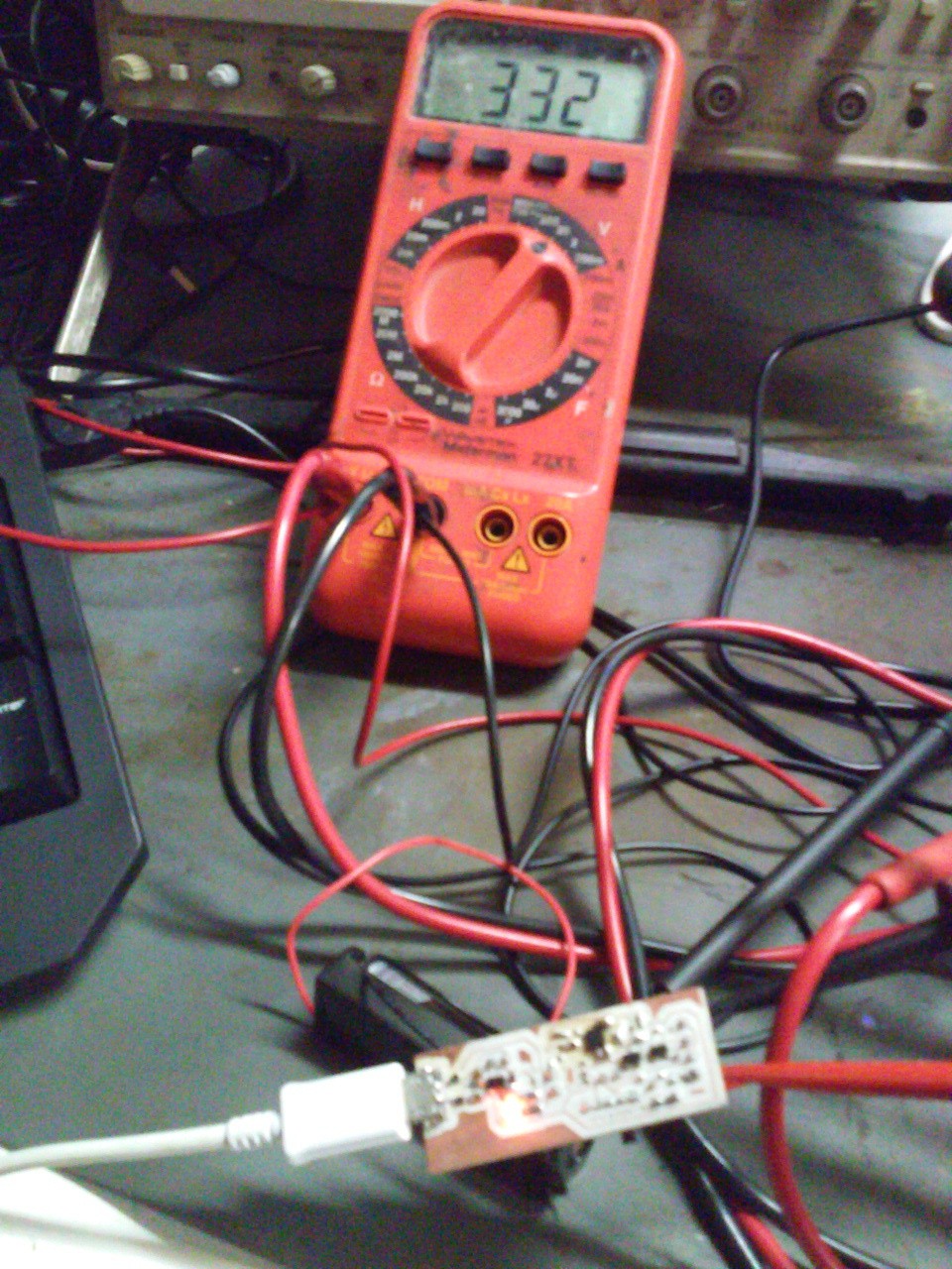
After some fiddling around on the board with the voltmeter and some tweezers I figured out the problem. I tried bypassing the FET with the tweezers and got a beautiful 3.3 volt output with the Alkaline, Li-Ion and USB power. I also tested 5 volts directly to the device but unfortunately this caused the output to jump up to 5 volts. It couldn't regulate the 5 volt input. Fortunately it didn't damage the chip.
It was surprisingly hard to find a Low Vgs P-Channel Mosfet in a SOT-23 package but after a bit of searching I settled on the MCH3383. Hopefully when it gets here everything will work.
Interestingly enough the -4.2 Vgs from a 10k to ground was not enough to turn on the FET either. I had to ground the gate with tweezers to get it to turn on with the Li-Ion installed. This wasn't enough for the Alkaline. I will probably have to rethink my resistor selection as well.
And if anyones interested here is what the TNC layout is looking like so far.
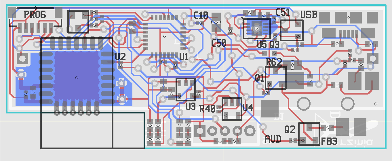
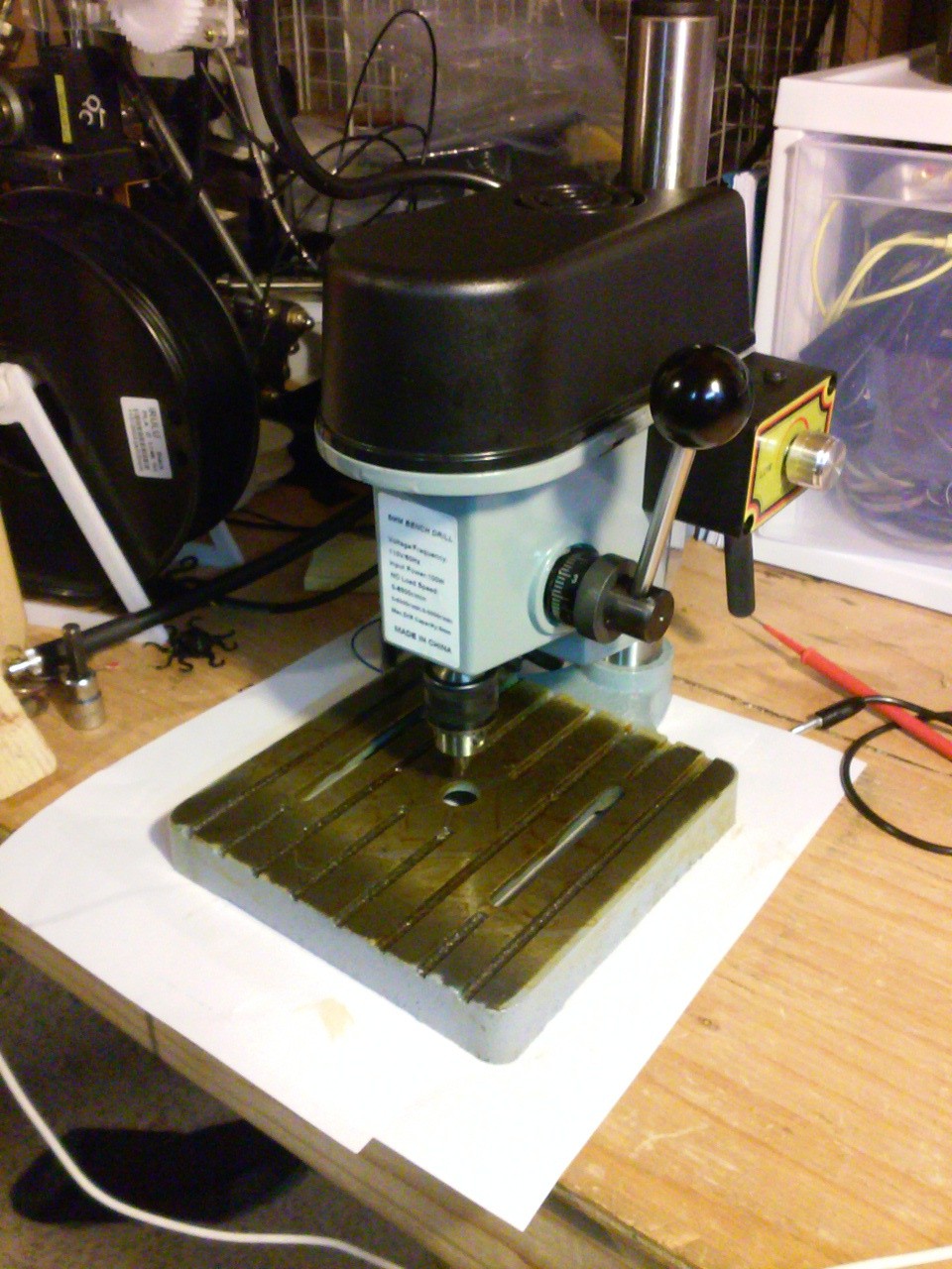
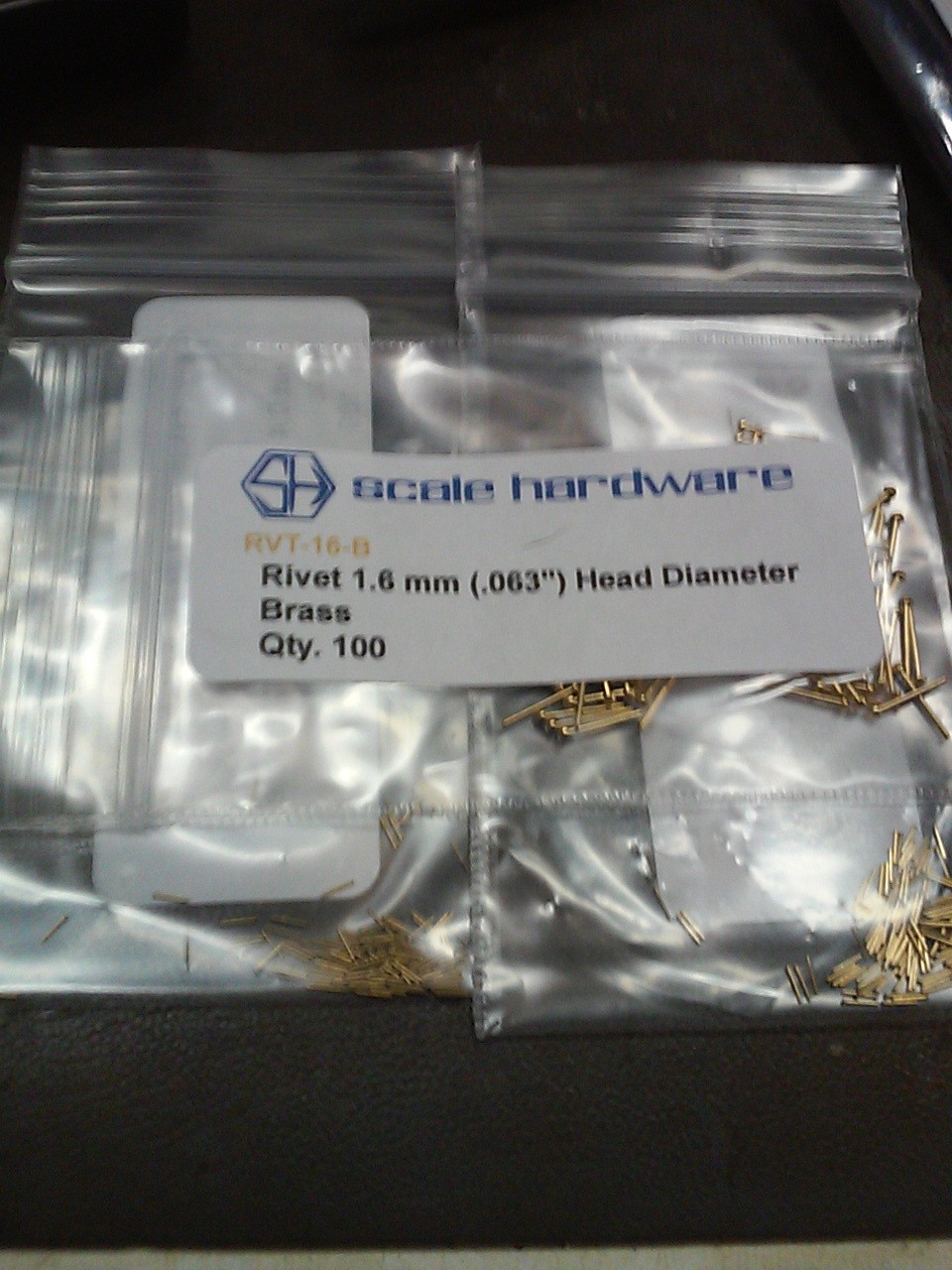
I'm using 25mil via holes and keeping them out from underneath parts to make it a bit easier to make the board at home. I just got a new Jewelers Drill press and a bunch of tiny rivets for PCB prototyping so I might even try using 13.5mil vias for the final version.
I changed from a SIP pinout for the programming header to a 1mm pitch rectangular connector so it could double as a GPS connector. I matched the pinout to the GP-635T. If anyone wants to make it a stand alone beacon with no need for a BLE capable master to tell it where it is they can populate this connector and add the GPS!
I'm also thinking of adding another connector footprint that will allow CAT control of the radio using a shared UART with the GPS.
I'm also hopping I'll be able to make the firmware decode 9600 baud packet from various radios discriminators outputs. As it stands I know it can modulate/demodulate 1200/300 VHF/HF packet schemes. I want it to be as capable as possible.
That's all that's been going on this last week. Hopefully I'll have a post with good news on the power supply design sometime next week with the new Mostfet and Resistors.
Discussions
Become a Hackaday.io Member
Create an account to leave a comment. Already have an account? Log In.