 Daniel L
About 15 years ago, a friend of mine (an enthusiastic Warhammer 40k player) asked me, if it would be possible to build a real working rocket launcher for one of his models. I do not play Warhammer 40k myself, but I admire the dedication and devotion of the players in building and finishing their models. This project never went beyond the conceptual phase, as we both started our academic career in different cities and didn't have the time to pursue our goal.
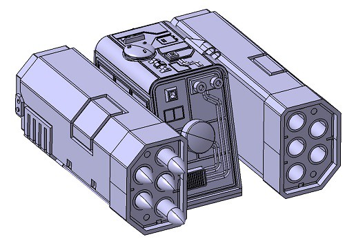
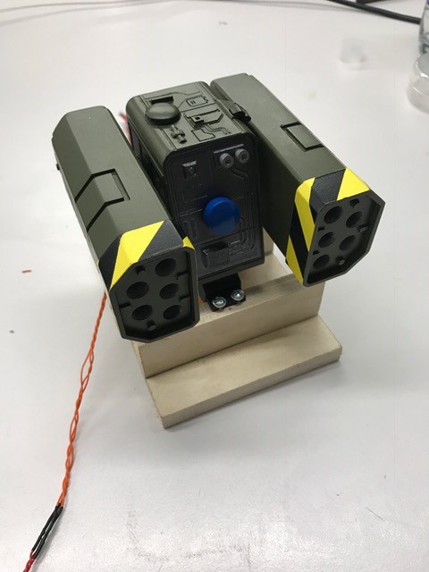
Some time ago, I found some 6 mm black-powder rocket motors in a junk box and decided to carry out this project. I was inspired by the Hyperios Whirlwind Warhammer 40k model. Unfortunately, I did not manage to build the model in the common 1:60 scale. It had to be a bit bigger, because the limiting factor was the diameter of the rocket motors.
Everything of this project is self-made. The mechanics were designed in CAD and manufactured on a 3D-printer. The pitch and yaw axis are driven by rc-model servo motors. The electronics incorporate a STM32F407 controller connected to a BLE-module. With a small IPhone app, the launcher can be controlled by a smartphone.
As I started the project, it was intended to be a small interlude between other projects. However, things escalated as I wanted to have a perfect result. At the point when I nearly finished the first version and figured out that the elevation servo was marginal too weak to lift the start boxes, I was close to dump everything in the trash can and move into a cloister. Finally, I started again from scratch and reworked the design. The whole project took me one year, and I didn't dare to sum up the hours of work as well as the money spent on this project (my girlfriend might kill me, if I do so...).
The following details of this project are also available in German under this link.
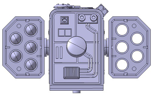
The first step was the design of the model in CAD. The total size of the model is defined by the aspect ratio of the rocket which again is defined by the diameter of the rocket motors. I used the so called MicroMaxx black powder engines which are the smallest commercial available rocket motor. First of all, the starter-boxes were designed, followed by the turret. The most time consuming part was the design of the details and applications.
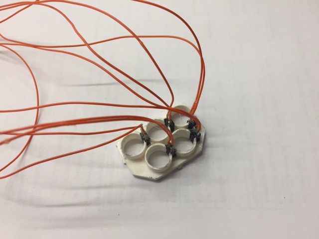
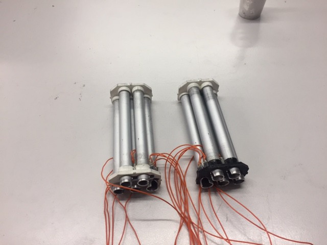
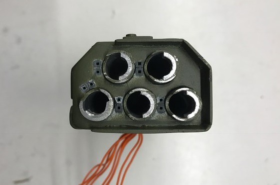
Nearly all parts were manufactured with a 3D-printer. I started with the back plates of the starter-boxes. These parts were equipped with the connectors for the electrical igniters. The connectors were glued into the back plate and wires were soldered to the connectors.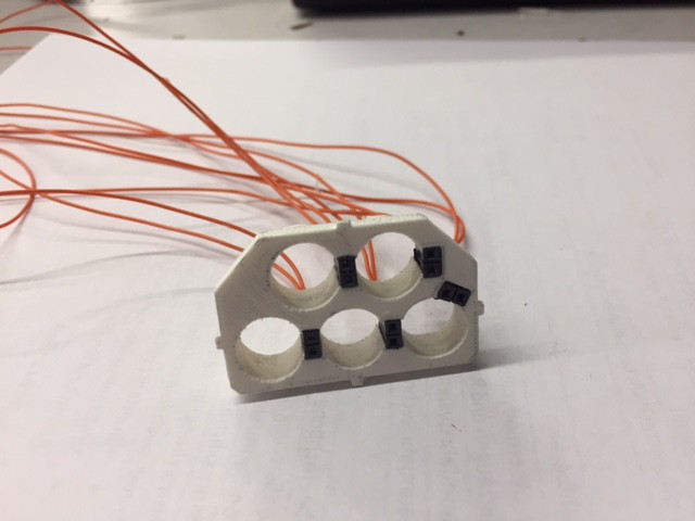
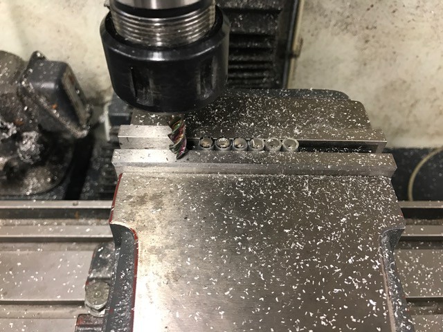
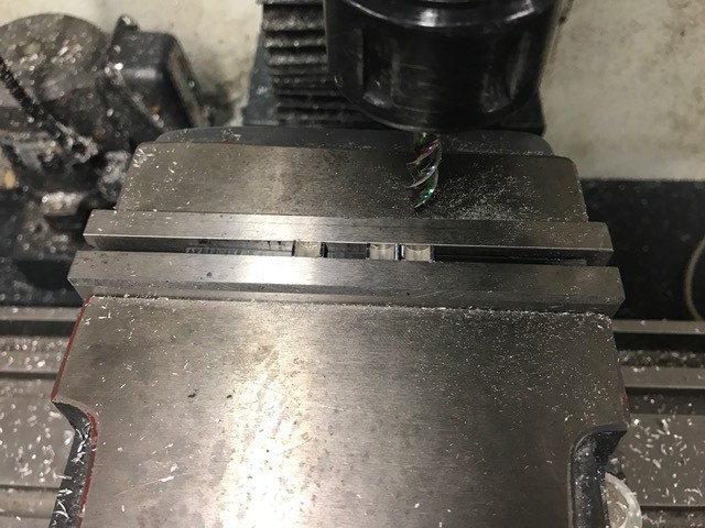
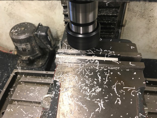
 In the next step I cut 10 aluminium tubes with an outer diameter of 10 mm and machined them to the correct length on a lathe. Every tube has a milled slot at one end for the ignition wires.
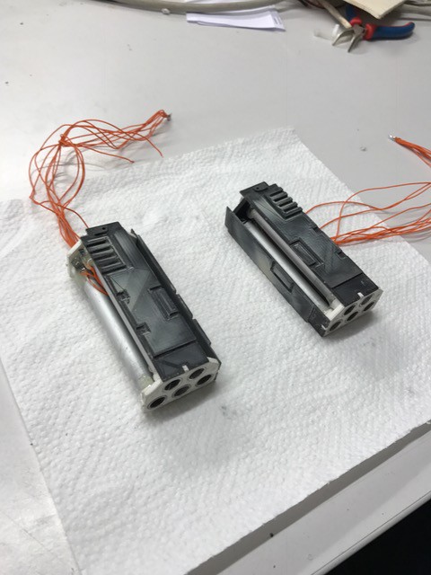
 After printing the front plates of the starter-boxes, the tubes were glued to the plates.
The starter-boxes are completed with 8 panels glued onto the lateral faces. This was indeed a lot of work. The parts from the 3D-printer do not have the ideal surface for painting. Thus, a lot of filling and sanding had to be done which was not easy due to the amount of details on the parts. The small gaps between the panels had to be mended as well.

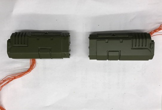
After an excessive filling-and-grinding-festival more details were applied to the starter-boxes.


In the next step, the boxes were painted.
The starter-boxes have fitted some kind of collar to their front end. These parts have a yellow-black striped painting. The painting of these parts was done before they were mounted to the boxes. I used a white primer so that the yellow painting looks very intense. Then, the stripes were masked using a self-adhesive stencil and the parts were painted black. In the first attempt I used standard acrylic spray paint. But the stencil left some residues from the adhesive surface on the yellow paint. These could not be removed without damaging the yellow paint. So I removed all the paint and painted the parts again, this time with 2-component paint. After the curing of the paint, the surface can be cleaned with paint thinner as the 2-component paint is not susceptible to solvents. After finishing the painting, the collars were mounted to the starter-boxes.
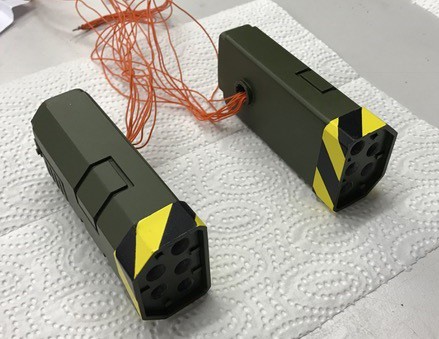
The last step to finish the starter-boxes was the installation of end stops in the launch tube so that the rockets will not fall out when the launcher is elevated. Therefore, 10 small rings were cut from an aluminium tube and milled to a height of 5 mm. Then, about 60% of the rings were cut away with the mill. The remaining parts were glued into the launch tubes.
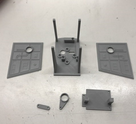
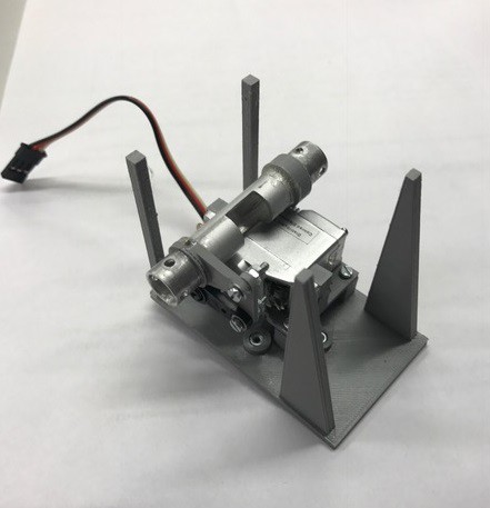
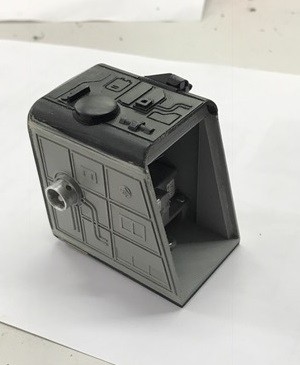
The manufacturing of the turret was started by printing the base plate, the side panels, the servo mount and the lever parts for the elevation mechanics.
The starter-boxes are fitted on an aluminium tube within the side panels of the turret. The tube has a cut in the middle where the ignition wires are guided into the turret. The small holes at the end of the tube provide a form-fitting joint when the starter-boxes are glued onto the tube. A lever is glued and doweled to the tube. A bar connects the lever with the lever of the elevation servo. The servo is screwed on the servo mount. The whole elevation mechanism is mounted on the turret base plate with screws.

Next, the side panels are glued to the base plate. The panels carry the tube of the elevation mechanics. Furthermore, two arcs and a spacer are mounted to the assembly.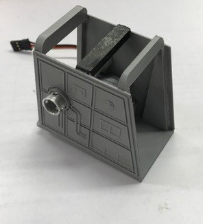 The back plate of the turret is a more complicated part, due to its many details. A lot of rework and fine tuning was necessary to yield a smooth surface for painting and to fill gaps between the plate and the adjacent parts.
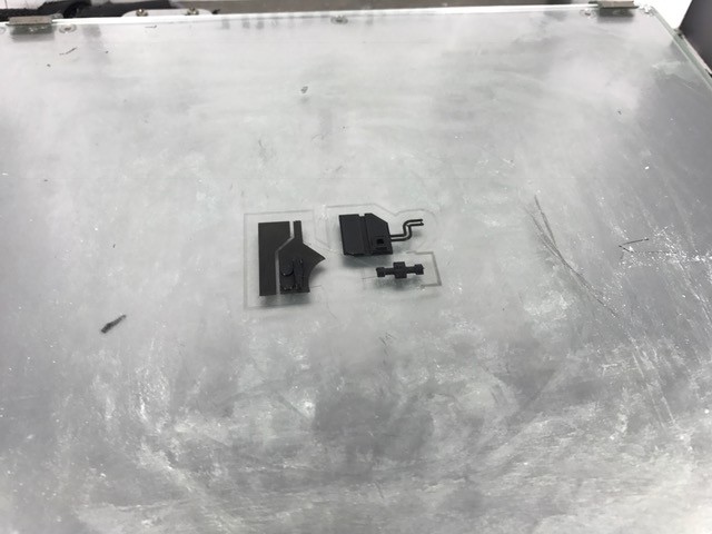
 Another challanging part was the cap of the turret. It is a thin curved structure with many details. To make it more easier to sand the surface for a good painting, I decided to seperate the printing process into the basic part and the details. After the reworking of the surface the details are glued onto the basic part.
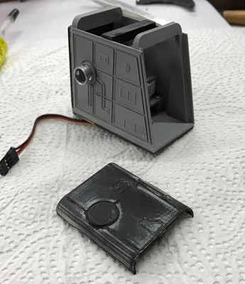
The cap was mounted on the turret together with a transition piece and all gaps were treated with filler. After some sanding, the turret was painted.

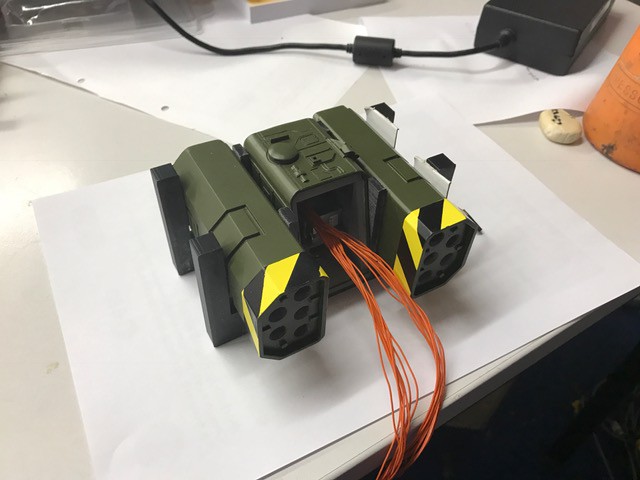
The most critical operation was the installation of the starter-boxes on the turret. First of all, the ignition wires were guided through the elevation tube. Epoxy resin adhesive was used to glue the boxes to the elevation tube. This had to be done very carefully so that the glue does not block the movement of the starter-boxes. There was only one try to do this correctly. In case of a failure, all components would have been lost. To achieve the correct alignment I printed a support structure, to hold the components in place.
The front cover of the turret was made from 4 3D-printed parts. They were painted separately before they were glued together. The front plate is fixed with double sided adhesive tape. This keeps the inside of the turret accessible.
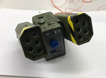

Next, the launcher was mounted on its yaw servo and the movability was tested.
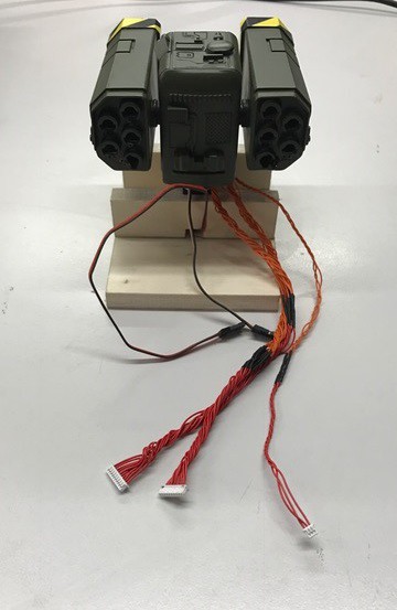
After checking the correct operation of the servos the cables were arranged properly and equipped with MOLEX Picoblade connectors.
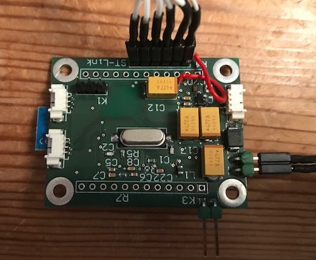
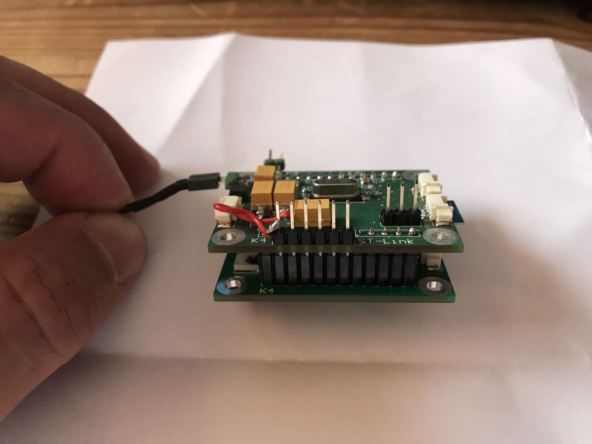
The electronics was designed with ALTIUM DESIGNER. It consists of 2 PCBs. One PCB contains the controller (STM32F407), a BLE-module (A20737A), voltage regulators and the peripheral components of the controller. The second PCB is equipped with a constant current source and MOSFET output stages for the igniters.
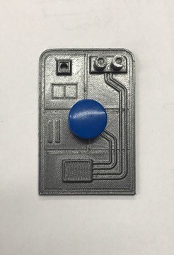
 The app for the IPhone was developed with the ANAREN Atmoshere IDE. This web based IDE allows to generate the code for the user interface on the smart phone as well as for the BLE module. It is the easiest way to develope simple BLE projects for your smartphone though it is a bit unflexible and not very powerful. The program features 2 slide controls for pitch and yaw movement. It displays the status of the igniters and has 10 pushbuttons to fire the rockets.
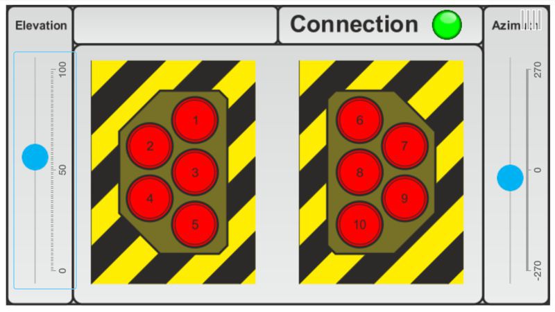
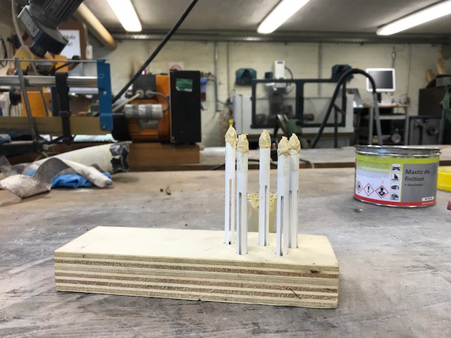
The rockets were manufactured from a plastic tube. The tube was cut into 10 parts which were machined to the right length on the lathe. The front end was drilled out so that the rocket motor fits into the tube. In the next step 4 slots were cut in each rocket on a mill to ensure a stable flight. The nose cones are 3D-printed parts. They are glued on top of the rocket and coated with filler. After the filled was cured, the nose cones were sanded on the lathe to achieve a smooth shape. In the last step the nose cones are painted using 2 component paint. The rockets are single use only.

This is a video of the first firing of the rocket launcher:
The target impact is quite remarkable, as well:
