 lion mclionhead
To save money on clothing, the decision was made to etch the Zoom replacement & the additional board for the ultimate vlogging mic on the same day. The zoom replacement undergoes continual evolution like everything else.
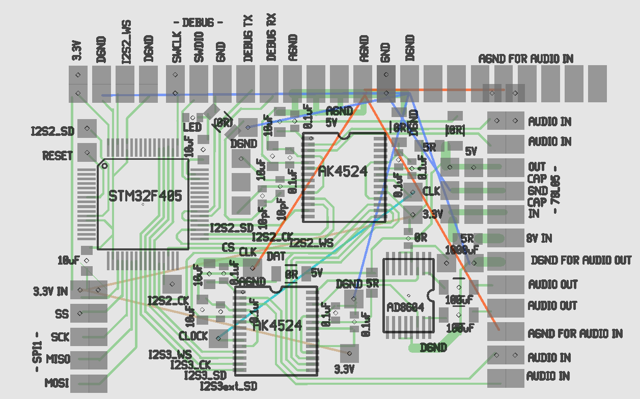
but converges on a mane ADC board which attaches to interchangeable front ends. The mane board exposes its spare I2S pins for an arbitrary I2S source. The lower ADC also provides a DAC for monitoring, so it's always connected & has to be the one taking input from any 2 channel front end. The upper ADC has to share its I2S pins with the aux input. They're obsolete ADC's, but easy & good enough. Digital & analog grounds were carefully starred.
The PI connects on the left. The front end connects on the right. The whole thing takes only 1.5" x 2", manely because of cost. Fully equipped with a front end, battery, & PI, it should be much smaller than a Zoom.
The 5V regulator is a pain. Need to test the impact of 5V power supply on the noise, again. The answer is FUGGEDABOUTIT. You can't use the PI's 5V for audio. The AK4524 actually drops its 5V to 3V internally. Its DAC is centered on 1.5V & the ADC is centered on 1V, but no further testing of the ranges was done. The theory behind powering the op-amp headphone driver off the digital 3.3V was the DAC only going from 0-3V. This would be much better off the 5V analog, but need to test the impact on the ADC.
It needs a dual balanced mic front end. Someday, it'll have a dual, unbalanced electret front end & a quad line input. The front ends are going to need their own microcontrollers, have a single UART wire for controlling pots, 3.3V digital, digital ground or just use analog pots & skip all that. They'll need 5V analog voltage & analog ground.
The audio inputs are wired to be balanced pairs. To use them without balancing, just leave 1 disconnected. Each goes to its own ADC with the summing in software.
It took a while to realize that all the STM32's can be programmed with just 2 wire "SWD" instead of the full JTAG port. This nugget came from tearing down a brushless gimbal & already having discovered the SWD mode inside an NRF51 dev kit. It saves immensely on board space.
Discussions
Become a Hackaday.io Member
Create an account to leave a comment. Already have an account? Log In.