 ogdento
BACKGROUND
My mother-in-law's house is a rambling single-story ranch built on a concrete slab and her master bathroom is over 50' from the hot water heater tank. Hot water runs through a great length of un-insulated copper pipe - installed under the slab - before it arrives at the bathroom sink. In the 2-3 minutes that it takes for the shower to get hot, more than 5 gallons of cold water has gone right down the drain!
Wanting to conserve water, my mother-in-law would catch the cold runoff in a five gallon bucket (or two) and use it for watering plants. That quickly became tedious.
Having to wait for hot water is a common problem and solutions include point of use heaters and hot water circulator pumps. Her plumber preferred hot water circulator pumps, so that's what she got. It failed, and this project details its resurrection.
WAIT, WHAT'S A HOT WATER CIRCULATOR PUMP?
Hot water circulator pumps cycle hot water through your plumbing lines so there is always hot water at or near the point of use. You no longer have to run your faucet, wasting water, while you wait for hot water to come out. Some pumps install at the hot water tank and others install at the farthest fixture. The pump pulls hot water from the tank and pushes the cooler water in the hot water line back to the tank via the cold supply, water heater fill valve, or a designated return line if you're lucky enough to have one.
Most pumps use a timer that can be set to run whenever hot water will be needed... typically during peak showering times. Usually they are set to run in the morning and maybe the afternoon but sometimes they are set to run *gasp* all day!
 There are also a few pumps out there that enlist a button press or motion switch to activate the pump, thereby making it an "on demand" pump. I think the on demand systems are the way to go... you have to wait a bit after you hit the button but you won't waste any water and the pump will only run when you tell it to.
...BACK TO THE PROBLEM
My mother-in-law's pump was programmed to run between 6:00 and 8:00 each morning. She didn't like running the pump for 2 hours a day when she only needed 10 minutes of hot water and although the pump is not obnoxiously loud, it is still audible and she didn't want to hear it kick on if she slept in.
Running the pump for 2 hours a day not only wasted electricity but her gas consumption also increased because circulating water back to the tank for 2 hours straight - through a large mass of cold concrete and earth - fired up the water heater for nearly the duration.
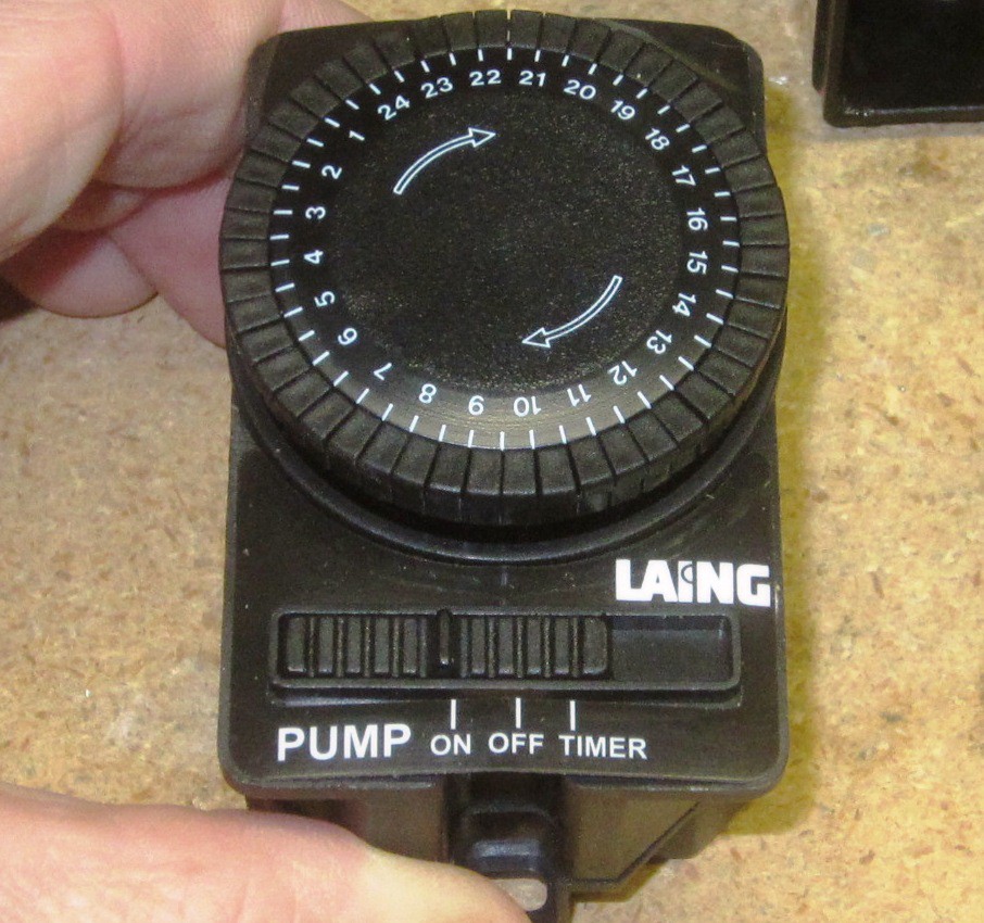
So, when the mechano-electric timer recently stopped working, I hacked it into an "on-demand" system.
ENERGIZING THE PUMP
The old broken timer was just a small motor that spun a dial, causing a heavy duty SPDT momentary switch to be engaged based on the up/down position of it's timer detents. When the switch was pressed the pump was energized.... so to get the pump to work, all I had to do was take the two wires from the switch and connect them together electrically (2 & 3 in the image below).
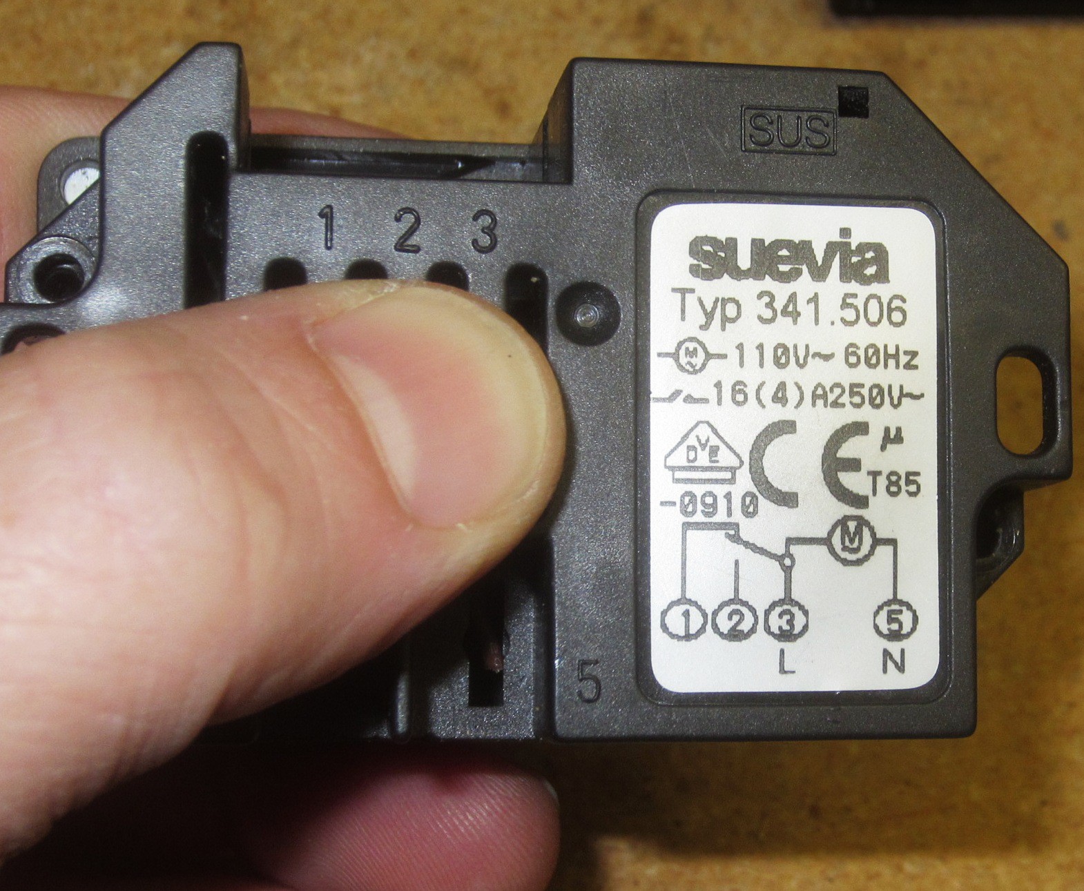
The label on the pump lists the motor as 98W at 115VAC, and some p = iv math gives us a current rating of 0.85A. The motor is an inductive load so the start up current could be 2-3 times that. I could have used a triac to handle the load, but my junk bin contained a controller board from a friend's recently deceased stove so I warmed up the desoldering iron...
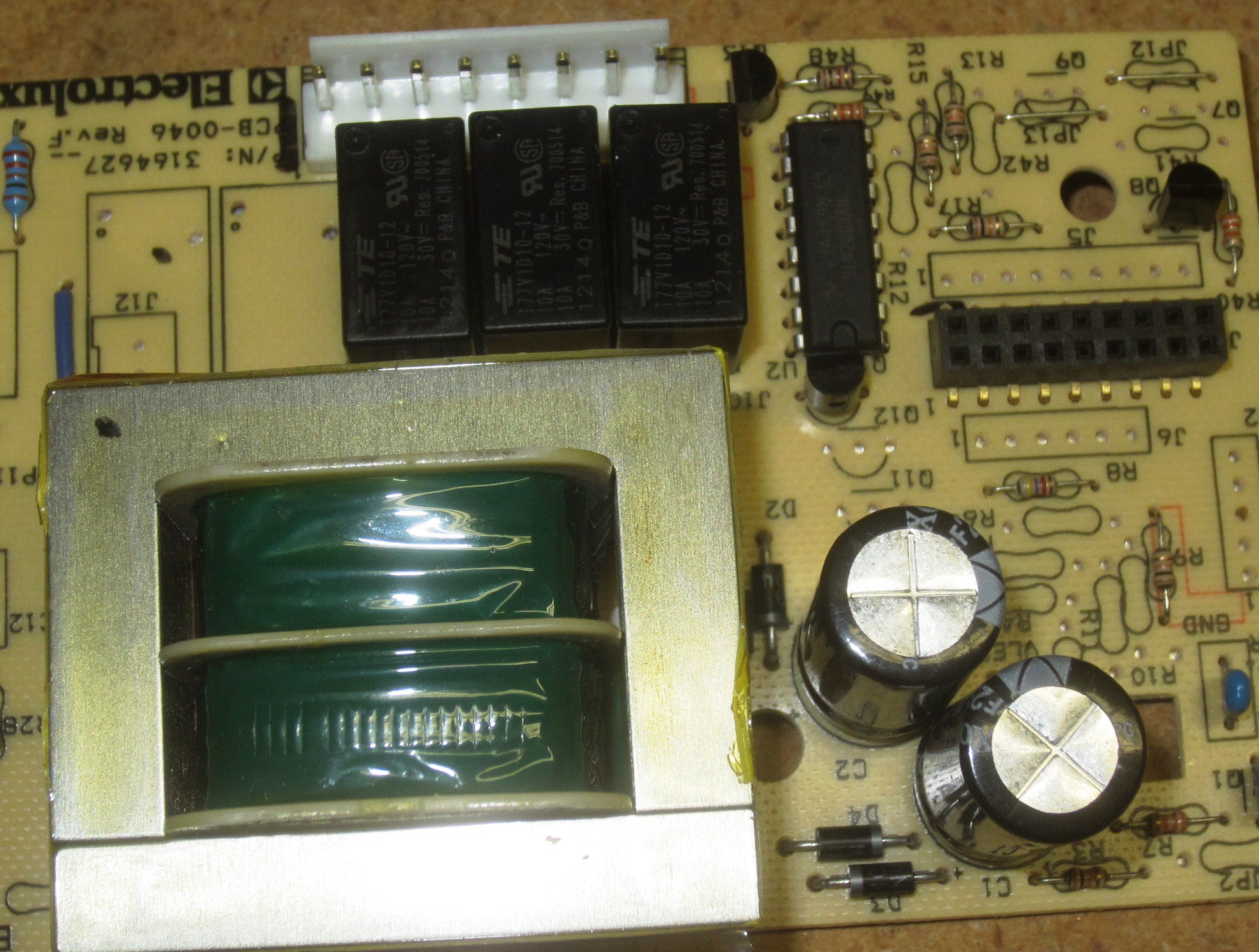
Who doesn't love sourcing parts from discarded electronics?? I probably could have bought all new bits for < 10 bucks but almost everything I needed was on the stove board. I got a 120VAC 10A SPST relay, an 1N4001 diode (to use as flyback), a 2N4401 NPN transistor to drive the relay, pcb mount spade connectors for the pump connection, some caps, and a few resistors. Besides the parts being free, I can assume they're not counterfeit... getting fake components online is a real pain.
I discovered that the pump itself has a controller that shuts it off when it senses hot water at it's inlet, so all I really had to do was energize the pump for as long as it takes to get the hot water. This typically took 2-3 minutes but on very cold days it took longer so I figured I'd use a 5 minute max run time.
THE CIRCUIT
If you can smell a 555 configured as a simple monostable multivibrator then your nose is working. This is the schematic:
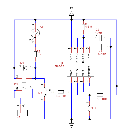 Knowing that I wanted t = 5 minutes (300 seconds), a little more math got me the component values:
t = 1.1 x R1 x C1
I had a 47 uf capacitor on my bench, so that's what I used for C1.
That left R1 = 300 / (1.1 x 0.000047) = 5.8 M ohms.
A 5.8 M ohm resistor is not common but I had a 4.7 M (10% precision) part instead. In theory the 4.7 M resistor could shave 58 seconds off my time (t = 1.1 x R1 x C1... t = 242 s), but it's only a 10% precision component and actually measured out at 5.1 M... so I called it good enough. That should give me 263 seconds.
Once I got the circuit on a breadboard, I found that I still got darn close to a 300 second pulse (290 or so). I didn't measure the capacitance of my 47 uf electrolytic, but it's relatively high value combined with a likely poor tolerance is probably what made up the difference.
CONSTRUCTION
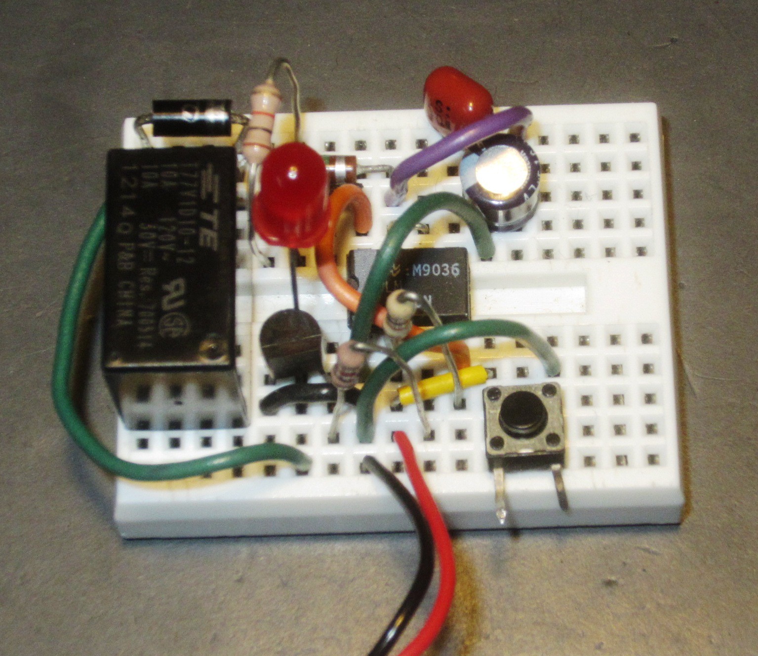
I've been using TinyCad to develop my hand-soldered, point-to-point type circuits because it exports to VeeCad which I can use to optimize my proto-board layout. I did a quick and dirty schematic, exported a netlist (in protel format), and imported it into VeeCad to fiddle with the layout. I then soldered everything onto a scrap of proto-board that just has solder holes - no traces - and it's kindof ugly but it works. Here's the final layout I got:
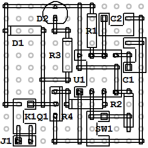
The actual relay is much larger than K1 on the layout, so I had to leave extra space.
Instead of populating SW1 and the LED (D2) on the board, I made a remote switch from an old doorbell button and hacked it to hold the LED. The switch/LED got mounted close to the sink, but the circuit itself lives in the old timer housing on the pump.
The timer/relay board got power from a 12VDC 1A supply from an old router.