To make the experience fit your profile, pick a username and tell us what interests you.
We found and based on your interests.
|
JPEG Image - 3.69 MB - 01/07/2018 at 01:26 |
|
|
XC8 seems to ignore negative array sizes in typedefs, a common trick for realizing static assert functionality in C. To get around this, the following code defines an unused file-scope function that declares an automatic array with negative size if the assertion fails, which XC8 properly complains about. If the assertion passes, the function gets defined, but is never called, and gets optimized out.
I disable the unused function warning to clean up the output a bit.
// disable unused function definition warnings
#pragma warning disable 967

#define _STATIC_ASSERT_H2(a, b) a ## b
#define _STATIC_ASSERT_H1(c, l) static void _STATIC_ASSERT_H2(_STATIC_ASSERT_LINE_, l) (){int a[1-2*(!(c))];}
// this will throw a negative array size when the assertion
//   fails at compile time; check line it was expanded from
#define STATIC_ASSERT(cond) _STATIC_ASSERT_H1(cond, __LINE__ )

STATIC_ASSERT(1 == 1);
STATIC_ASSERT(1 == 0);
this is mostly here so I can search for it later.
This weekend, I was testing the reverse recovery time of some diodes for a project. I decided to use my Siglent SDG1025 DDS because, you know, DDS! What I tried doing was setting the two channels to identical parameters (square waves at 1 MHz) to use one as a scope trigger. No matter what I tried, the outputs always showed some bad quantized jitter relative to each other. Here, I'm triggering on ch2 (bottom trace), and the jitter in steps of 2.5 ns is visible on ch1.
I played with the thing long into the night trying to get it to work correctly, but no. I even copied the parameters between channels using the channel copy function in the Utility menu. No dice.
I woke in the middle of the night wondering if this was a firmware bug. So, this morning, I grabbed the latest firmware and installed it. Of course, it turned all the menus into Chinese.
I found a document on how to fix this, and was soon on my way. The result: slightly less horrible broken-ness. It's still broken, though.
There really shouldn't be this kind of jitter between the two channels.
I've decided to make a dedicated tester for diode reverse recovery time. The edges on the SDG1025 aren't really up to the task, anyway.
So your stuff ain't working right? Need to scope some signals on a lashed-together prototype? Try cutting your jumper wires in half.
Strip some insulation off the new ends, then solder them back together. Now, you can connect scope probes to the lines. In this case, I was debugging some I2C: wrong address, as it turned out. I stripped more insulation off the black jumper for the ground connection since it has to accommodate two ground clips.
Answer: less than 500ps Tpd, sometimes. I built a gated ring oscillator with some single-gate 74AUC packages just to see how fast it would run. The 74AUC family seems to offer the fastest CMOS gates you can buy at at moment, guaranteeing a 1.6 ns max propagation delay at 2.5V. It looks like they can be significantly faster in practice, especially if you crank up the voltage a little :-)
The circuit is very straightforward. A 74AUC14 Schmitt-trigger inverter buffers the incoming gate signal. The output of this buffer gates the oscillator through a 74AUC00 NAND date and also drives a 74AUC04 for an output driver. The ring oscillator itself consists of two additional 74AUC04 inverters plus the NAND gate. Finally, one more 74AUC04 inverter is used as a driver to buffer the output. 453-ohm resistors are used at the outputs to create 10x dividers when combined with 50-ohm terminated oscilloscope inputs. The 74AUC gates are plenty fast, but don't source/sink enough current to drive 50-ohm cables directly, necessitating the use of these 10x "probes."
I'm running them at 3.3V, which is within their absolute max voltage of 3.6V, although the datasheet says they're recommended for up to 2.7V, and optimized for 1.65-1.95V supplies.
So, how fast are they? The oscillations start 410ps after the gate signal edge and run at 360 MHz. This frequency implies a mean propagation delay for the inverters and the NAND gate of 463 ps. That's very fast for gates you can essentially treat like your normal CMOS friends (except, of course for the fast edge rates, discussed below).
While the oscillator startup time of 410 ps is impressive, this circuit generates runt pulses at the end of the gate interval, unless the gate time happens to be an even number of cycles of 360 MHz. You can see a runt pulse generated at the rising edge here:
If this oscillator were driving a counter, that last pulse might or might not be counted. And, of course, the actual oscillation frequency will vary with voltage, temperature, and individual parts. Actually using this thing would be a non-trivial exercise in calibration.
I'm impressed with the 74AUC gates. When I built a similar circuit with 74AC gates, which I used to consider "fast," I measured a startup delay of 2.5 ns and frequency of 76 MHz. This circuit starts up 6 times faster and oscillates almost five times as fast. I think the only way to go faster is to switch to ECL parts, which I might as well try since I've gone this far.
While I had the circuit on the scope, I took a look at the edge rates from the 74AUC04's. The rise time was 560 ps and fall time 528 ps. This is not much faster than the 74AC gates which I measured at 700 ps and 650 ps, respectively. This may be part of the reason the 74AC series had such a reputation for bad behavior - the sharp edges manifest transmission-line effects on relatively short traces, even though the clock rates may not be that high. The 74AUC gates, on the other hand, actually seem to show propagation delays shorter than their edge rates, which is impressive - but I'm not convinced this is the case yet. I'm waiting on a few adapters so I can connect these outputs directly to the scope without using cables. At these speeds, dispersion in the cables might be affecting the edge rate measurements.
EDIT 20181226
@Yann Guidon / YGDES asked about frequency vs supply voltage. Here it is:
The datasheet says 0.8-2.7V, but it worked down to 0.6 and a little below in my tests. You could probably make a half-decent PLL with this thing, especially below 200 MHz.
What good is a male-to-female BNC adapter? At first, they don't make a whole lot of sense. Then, you realize that you are switching probes on your expensive oscilloscope a few times with each visit to the lab, and the connectors have a limited number of mating cycles.
This is especially true if you purchase vintage equipment. The solution - throw on some BNC-BNC adapters and leave them there. When they wear out, they're a lot less expensive to replace than the scope's connectors. It's not an original idea - these things are called "connector savers" for a reason.
The biggest drawback is that you can't use fancy probes which use the other connections behind the BNC, but I can't afford those kinds of probes anyway (even a single new passive 1 GHz probe costs more than I paid for the scope). A second issue is that it's easy to knock into the connectors when moving the scope or working around it because they stick out a bit - you just need to be a little more careful.
This is not the place to use cheap ebay connectors. I sprang for genuine Amphenol parts - sure, they're $12.62 each at Digikey, but that's a lot less expensive than replacing the connectors on this scope.
Glitches are bad. Don't let them ruin your logic design. But if you're really making an analog circuit which needs a short pulse, maybe glitches are just the ticket. In this case, the "classic" glitch generator produces 1.33 ns pulses using a 74AC02, because that's what I had on hand. The edge rates are a respectable 700 ps (rise) and 650 ps (fall). That's not bad for a through-hole part.
The circuit is the same one they tell you never to use in your logic designs - it will surely mark you as a newb. Go ahead and do it anyway.
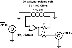
A trigger pulse is supplied from an external generator. A first NOR gate is used to buffer the signal, while a second delays and inverts the pulse. The difference between the inverted/delayed edge and the original signal drives the output NOR high for a brief period - the propagation delay of the middle gate.
This delay varies with voltage and temperature, so the pulse width will, too. But if you just need a pulse near the correct width, this might be good enough. For longer pulses, you could add more gates or a simple RC integrator in the delay path.
The whole thing is dead-bugged on some copper clad. All my circuits look alike - ugly.
I don't think that ringing after the pulse is due to poor termination. The circuit is pretty compact, and the line to the scope is terminated at both ends. Instead, I think this is the classic ground bounce issue associated with the 74AC series. If you zoom out, you can actually see the same "ringing" happening at the falling edge of the trigger pulse, too - even though there's no output generated at that point. It's clearly visible (9th division below) and has the same shape as the ringing after the output pulse. The time between the two is around 62ns (the trigger pulse width), and I sure don't have any 30 foot cables in the setup. Is this just ground bounce from the other two gates switching with the falling edge of the input pulse?
I measured very, very carefully and determined that a hacked Tektronix TDS754D would, in fact, fit down my chimney :-) It turns out that Rigol wasn't the first to sell (almost) the same hardware as different scopes: the 500 MHz '754 can be hacked into a 1 GHz '784 by removing a few capacitors.
The one I found had already been "fixed," so it was ready to go. To check the bandwidth, I scoped the tracking generator output from my spectrum analyzer which goes to 1.5 GHz, and is pretty flat, amplitude-wise. Set to zero-span mode, the analyzer makes a nice sine-wave generator. I first measured the amplitude of a 100 MHz output at 712 mVpp, then cranked up the frequency until the amplitude dropped by 3 dB (= 0.7071 * the original amplitude). The number to hit was 504 mVpp, and I found it at 1.05 GHz, right where it should be for a 1 GHz scope :-)
This is an old scope - it uses a 3.5" floppy to save data. I had to order a USB floppy drive ($12), which surprisingly is cheaper than a box of disks ($20). Luckily, my spouse found a few disks in an ancient laptop bag.
I happened to have a 640x480 LCD monitor from around 2002-2003 that still works, and it hooks right to the VGA output of the scope, so I'm protected if the CRT goes bad.
I dug through the "Q" box last night and found my bag of 2N2369 transistors, so I can make an avalanche pulse generator and check the rise time, too.
This is my first Tek scope, even though it's an old one. So far, I'm very happy with it. It even has that "old electronics" smell -- kind of like the old-book smell first-edition collectors relish.
There have been a few times when I needed an oscillator I could start very quickly, with a small timing jitter. I had never really found a good solution, until now. Looking through a datasheet for a time-to-digital converter, I saw they used a gated ring oscillator for timing. I quickly threw together a prototype using a 74AC02. The enable input is able to start the oscillator in 2.5ns, with a standard deviation (jitter) of only 68ps.
The circuit is extremely simple. One NOR gate from the package is used as a buffer and inverter for the gate signal input. The remaining three NORs are connected as a ring oscillator - two of them as inverters, and one used to gate the oscillation - it's an inverter when the other input is low. 39 ohm resistors are used to source terminate the signals sent to the oscilloscope to avoid reflections on the cable. The cables to the oscilloscope are the same length.
The scope image below shows what's going on here - when the enable input goes low, the oscillator starts up - and very quickly. You can see the relevant measurements at the bottom of the screen.
The enable input is able to start the oscillator in 2.5ns, with a standard deviation of only 68ps. This is pretty good for something thrown together in a few minutes. Once started, the oscillator runs at 76MHz - a version with one NOR (or NAND) gate and two inverters would probably run faster, although the start-up time is dependent on the 2-input gate.
The oscillator output could be used to drive a counter for measuring the period of short pulses, or could be divided down to drive the clock input of a microcontroller for synchronizing code with an incoming signal. Of course, the frequency of the ring oscillator depends on temperature and supply voltage, so any system using this technique would have to calibrate periodically if accurate timing was required.
I think I'm going to make another version on a PCB with two 74LVC1G04's and a 74LVC1G00 to see how it works.
I like to prototype with 30ga kynar-insulated wire-wrap wire, commonly seen in blue. I think everyone on the planet does re-work with the stuff, too. There's a trick to stripping the insulation without going crazy. If you cut and strip the wire in the usual manner, often the whole insulation slides right off, which is extremely frustrating. Maybe people already know how to avoid this, but I figured I'd share it just in case. It took me years to stumble on to it. The trick is to only strip one end, and do it while the piece is still on the reel (before cutting to length).
Strip off twice as much insulation as you want on each end. Do this while the wire is still connected to the reel.
Cut the wire to length.
Slide the insulation to expose the wire on both ends.
Happy soldering!
There was a discussion on hackchat about garage reflow processes. I happened to be assembling three small PCBs today, so I figured I'd take some pictures and document how I do it. I don't think anything I do is really original, but I've stolen a set of techniques that work together. Here are the tools of the trade:
I transfer solder paste from the larger syringe it comes in into 1 ml ones. These syringes are much easier to dispense from and control accurately. I use two different blunt needle sizes, 22 ga and 25 ga. The 22 is useful for SOIC-sized components, while the 25 is better for smaller pitched components. I have some 27's on order, because I think 22/27 is probably a better combination. You can see the air bubbles in the syringes. You should try to avoid these, because they add a springiness to the dispensing that makes it a little more difficult to control. I used to take better care to avoid them, but at this point I just deal with it.
I dispense the paste with my thumb on the plunger, resting my hand on the bench. It's surprisingly easy to do this accurately after a little practice.
Every once in a while, either due to air bubbles or my hand heating and expanding the paste, too much will flow. I wipe the excess on a scrap of paper towel.
How much paste do I use? I don't know. I've found that excess paste usually doesn't cause too many problems. I occasionally get a bridge or two on 0.65 or 0.5mm pitch components, but mostly you just get solder balls which are easily removed (see below).
After applying all the paste, I place the components with tweezers.
Sometimes, the paste gets on the tweezers and the flux makes them stick to components. Wipe the tweezers with a paper towel (moistened with 90% isopropyl alcohol in tough cases) if this happens.
I make a component map in Eagle to know what's going where:
You can see the components on the solder paste here. It doesn't have to be a very precise operation. Solder paste is amazingly resilient and fixes a lot of your mistakes. For fine pitch components, it's OK to just lay a single bead along all the pads. The paste will do the rest. You can see where I used an 0603 cap on 0805 pads. I can never tell just by looking at them.
I reflow the boards on a cheap hotplate. This particular one has a flat surface that works pretty well:
I turn it half way up, which I tried the first time I used it several years ago, and have just stuck with. I wait until the surface approaches 200C, measuring it with an IR thermometer.
I'm using 63-37 leaded solder here, which melts at 183C. The hotplate will continue to heat after I place the board on there, getting up to around 240 or so. If you are using the usual lead-free solder, you will want higher temperatures, and with tin-bismuth solder (I have some on order), lower temperatures.
Once the hotplate is around 200C (and rising), I place the board on there.
I just watch the paste. When it turns silver and shiny, and all the parts get pulled into position, it's done. I pay careful attention to larger components (especially USB connectors) which sink heat away from the PCB. These melt last.
Once the PCB is done, I take it off the hotplate with a spatula and let it cool relatively slowly. Sometimes I rest it on a block of wood. After it has cooled, I check all the joints with a low-power inspection microscope. A magnifying glass or younger eyes would probably work just as well.
Here you can see what happens when you apply too much paste - you get solder balls. Luckily, there's an easy cure for this condition. The balls are just held onto the PCB with flux. You could wash the PCB in isopropyl alcohol to remove the flux, but I just pick off any solder balls with...
Read more »
Create an account to leave a comment. Already have an account? Log In.
I have seen that on the web before. But I've melted my share of breadboards (with hot transistors, for example), and wasn't sure how well they would hold up to soldering.
Become a member to follow this project and never miss any updates

 Ted Yapo


This is how I do but with a breadboard instead.