 lion mclionhead
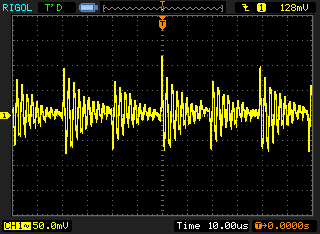
The ripple coming out of the phantom power is 100mV at 100khz but it's canceled out by the differential signal. The loss would be from the head room. It's not affected by the gain. Since it's not affected by the gain, the lion kingdom would almost say it's a probing artifact.
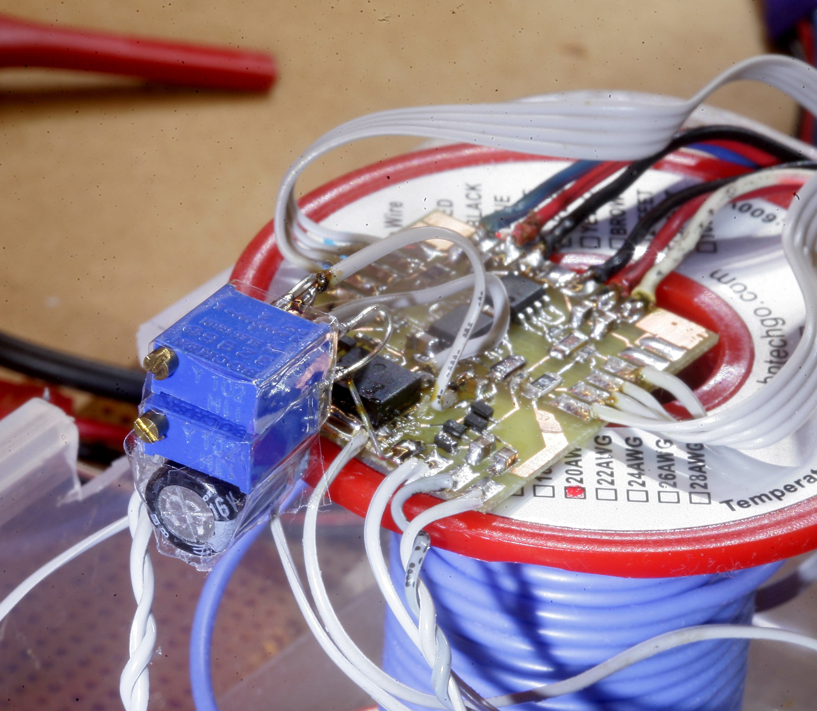
A bag full of commercial boost converters capable of creating phantom power & powering lighting was on the wishlist. Behold the mighty XL6019 reference design.
https://www.amazon.com/s?k=xl6019&i=electronics&ref=nb_sb_noss_1
There's a review showing it being limited to 40V, but it can probably be hacked to 55.
The datasheet claims 60V as the absolute maximum.
http://www.xlsemi.com/datasheet/XL6019%20datasheet-English.pdf
No-one reviews the ripple at high voltages, but they're probably no better than the home made boost converter since all switching converters are noisy. The best option might be just using a faster microcontroller for the home made boost converter. No-one has torn down a Zoom recorder enough to reveal any secrets, but the lion kingdom suspects they use noisy switching converters.
The only gear making truly flat phantom power would manes powered. That would use a toroid transformer & linear regulator. No-one tears down pro audio gear.
Lions have run the pre-amp on a Rudung switching converter with no problems. The differential signal cancels out effectively, despite being in software. It would be worthless for a non differential electret microphone, however.
Then the lion kingdom noticed clipping in a voiceover that was well below the full range of the waveform.
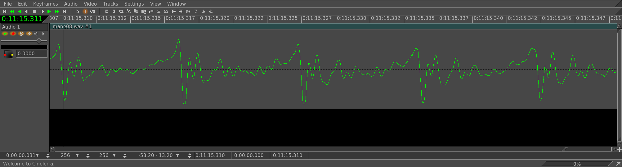
Could this have been the loss of headroom caused by the ripple? The ripple should have made clipping look more like noise than a flat line.
The preamp famously used a fixed 5V regulator which was known to limit the peaks slightly below the full range of the 5V ADC's. It was only a 2dB loss on the meters. That didn't seam like a lot until the lion kingdom saw how many pixels it was from the waveform edge. A variable regulator would be required.
2 tongue angle adjustments were required for the voltage regulator & for the virtual ground. It needed a 6V & a 3V to completely reach the rails. The LF353 op-amps had a 0.5V dropout voltage on the high & low ends.
Discussions
Become a Hackaday.io Member
Create an account to leave a comment. Already have an account? Log In.